


For Machines Mfg. Since 5/11 13" x 40" Heavy 13
®
EVS Lathe
-25-
PREPARATION
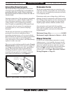
Test Run
After all preparation steps have been completed,
the machine and its safety features must be
tested to ensure correct operation. If you discover
a problem with the operation of the machine or
its safety components, shut the machine down,
disconnect it from power, and do not operate it
until you have resolved the problem.
A Troubleshooting section is provided, starting
on Page 83, to assist you with solutions if a
problem occurs or if the lathe does not function
as described in this section.
If you need additional help after reviewing the
troubleshooting section, or you are not confident
troubleshooting the machine on your own,
contact our Tech Support at (360) 734-1540.
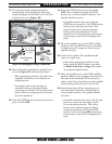
To test run your machine:
1. Make sure the master power switch (see
Figure 21) on the rear of the machine is
turned OFF.
2. Read and follow the safety instructions
at the beginning of the manual, take all
required safety precautions, and make sure
all previous preparation steps discussed
in this manual have been followed and
completed.
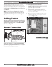
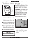
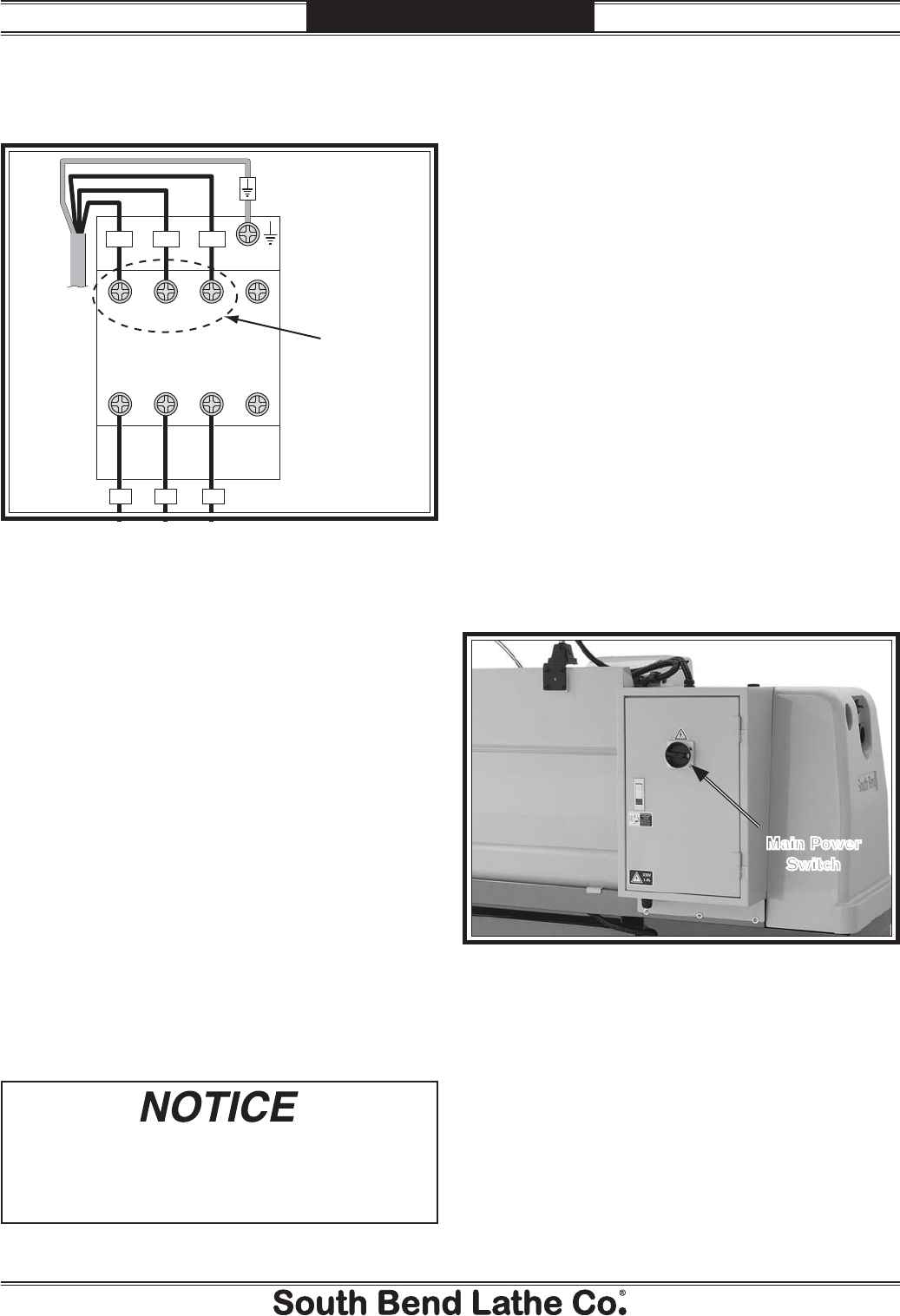
Ground
L1 L2 L3
Master Power
Switch
To Power Source
HOT HOT HOT
6T3
N
N
4T22T1
5L33L21L1
Connect
incoming
HOT
wires here
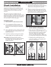
Figure 20. Power connection at master power switch.
5. Connect the incoming hot wires to the upper
master power switch terminals
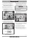
6. Make sure the power cord and wires have
slack between the strain relief and terminal
connections so that they do not bind, then
tighten the strain relief to secure the cord.
Note: The strain relief must be tightened against
the outer jacket of the cord. Avoid over-
tightening the strain relief or it may crush
the cord and cause a short.
7. Test the strain relief to ensure it is properly
tightened by pulling the cord from outside
the box with light-to-moderate force. When
the strain relief is properly tightened, the
cord will not move inside the cabinet.
8. Close and lock the main electrical cabinet
door.
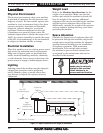
To avoid unexpected start-up of lathe
components, keep the master power switch
turned OFF until instructed otherwise in the
Test Run.
Figure 21. Location of the master power switch.
Main Power
Switch
4. Connect the incoming ground wire to the
ground terminal directly above the master
power switch, as illustrated in Figure 20.