-94-
For Machines Mfg. Since 5/11
13" x 40" Heavy 13
®
EVS Lathe
ELECTRICAL
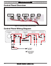
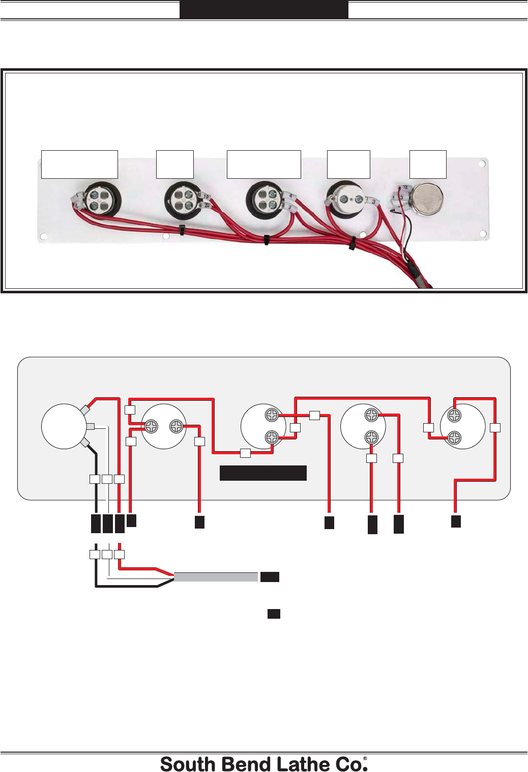
Control Panel Overview
Control Panel Wiring Diagram
TB
3
TB
TB
4
TB
1
PCB
1
PCB
PCB
20
PCB
JOG
PCB
2
PCB
3
Control Panel
(Viewed from Behind)
Spindle Speed
Dial
Power Light Coolant Pump
Switch
Jog Button STOP Button
X2(-)
3
4
NO
3
4
NO
1
2
NC
X1(+)
3
3
3
3
4
20 19
3 1
2
14 13
13
12
1214
2
nd
2
Spindle Speed
Dial
Power
Light
Coolant Pump
Switch
Jog
Button
STOP
Button
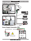
Figure 141. Control panel wiring (viewed from behind).
TB
Electrical Cabinet
Terminal Board
(Page 92)
Circuit Board
(Page 93)


