


For Machines Mfg. Since 5/11 13" x 40" Heavy 13
®
EVS Lathe
-79-
SERVICE
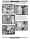
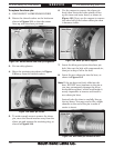
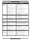
10. Push the pedal lever down to verify that the
cam lobe pushes the brake switch plunger in.
When pushed in, the switch should click.
— If the switch does not click, loosen the
switch mounting screws, push the brake
pedal all the way down, and move the
switch closer to the lobe until it clicks.
Secure the switch in place at this location.
Note: In the released position, there should be an
approximate 3mm gap between the switch
plunger and the cam lobe.
11. Re-install the motor access panel, connect
the lathe to power, then test the brake
pedal. If you are not satisfied with the brake
performance, repeat this procedure until you
are.
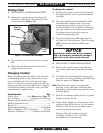
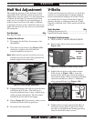
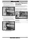
9. Locate the brake switch shown in
Figure 129.
Figure 129. Brake switch and pedal cam.
Brake
Switch
Pedal
Cam
Leadscrew Shear Pin
Replacement
Tools Needed: Qty
External Retaining Ring Pliers #1 .......................1
Magnet ...................................................................1
Safety Goggles .......................................................1
Blow Gun w/Compressed Air ................................1
Light Machine Oil ..................................As needed
The leadscrew is secured to a connecting collar
that is part of the headstock drivetrain with
the use of a soft-metal shear pin. The shear pin
is designed to break and disengage the power
transfer to the leadscrew to help protect more
expensive lathe components in the case of a
carriage crash or the lathe is overloaded.
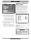
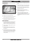
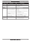
Contact South Bend to order a replacement shear
pin (Part Number PSB10121234) or use the
specifications in Figure 130 to fabricate your
own.
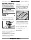
If you fabricate your own shear pin, make sure
to use the material and dimensions specified
in Figure 130. Otherwise, the shear pin may
not provide the intended protection and lathe
damage could result.
9mm
7mm
5.8mm
0.5mm
0.2mm
0.2mm
3mm
NOTE: Shear Pin Material = S45C (SAE 1045)
Figure 130. Shear pin specifications.