


-26-
For Machines Mfg. Since 5/11
13" x 40" Heavy 13
®
EVS Lathe
PREPARATION
3. Clear away all tools and objects used during
assembly, lubrication, and preparation.
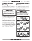
4. Make sure that the chuck and jaws, if
installed, are secure (refer to Chuck and
Faceplate Mounting on Page 31).
Note: If a chuck is not installed on the lathe, you
do not need to install one for this test.
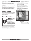
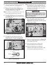
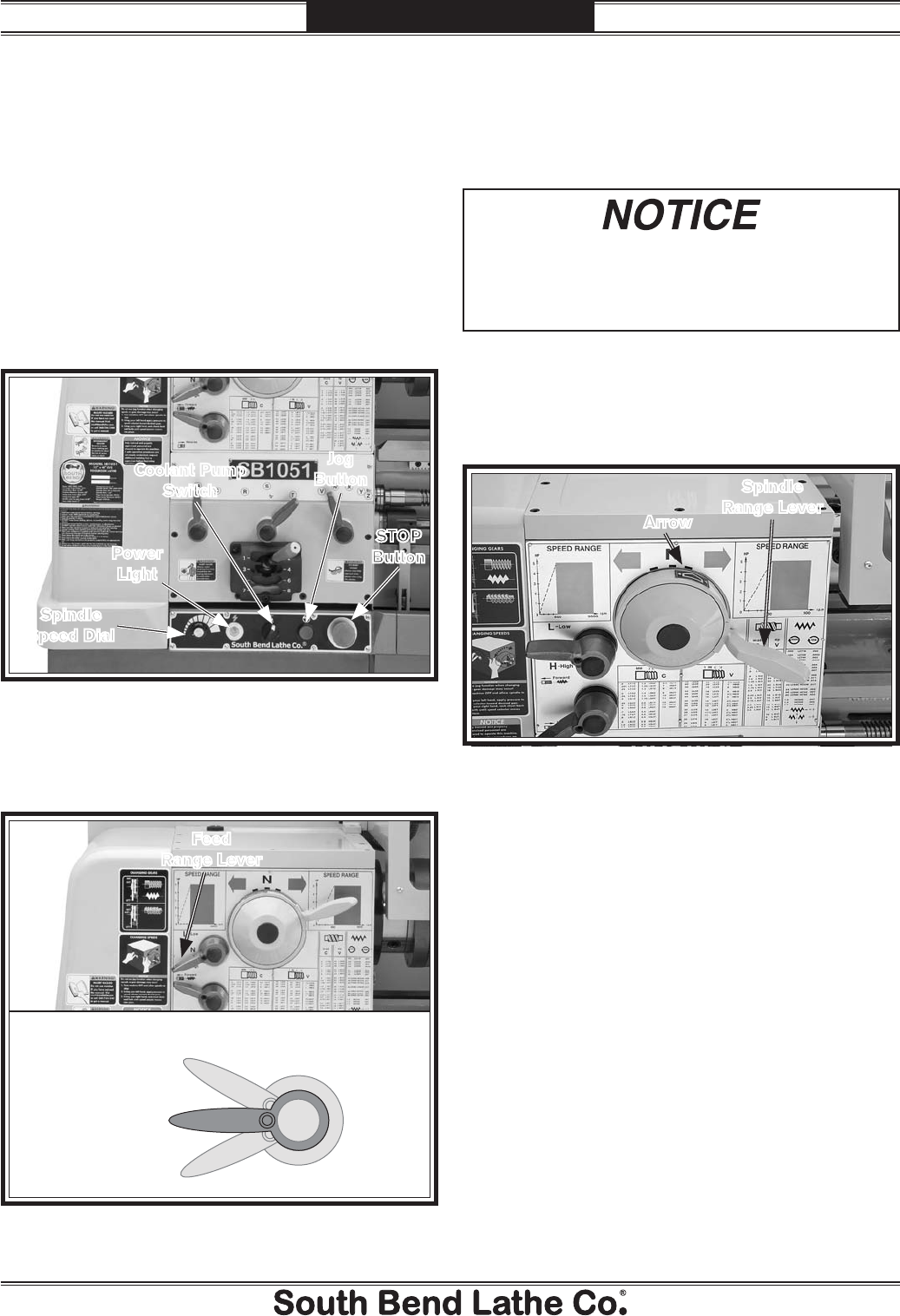
5. Push the STOP button on the control panel
(see Figure 22), and point the coolant nozzle
into the chip pan.
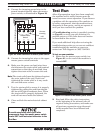
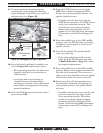
6. Disengage the quick-change gearbox by
moving the feed range lever to the neutral
(middle) position, as shown in Figure 23.
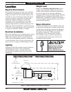
7. Move the spindle speed range lever so the
arrow on the hub points to the right (see
Figure 24). This will make the lower spindle
speed range available.
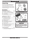
Figure 22. Control panel components.
Spindle
Speed Dial
Power
Light
Coolant Pump
Switch
Jog
Button
STOP
Button
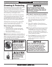
Figure 23. Feed range lever.
Low
Neutral
Feed Range Lever
High
Feed
Range Lever
DO NOT use the jog button to help mesh the
gears when changing spindle speeds or speed
range! Doing so could damage the gears and
connected components.
8. Rotate the spindle speed dial (see Figure 22)
all the way counterclockwise to set it at the
lowest speed for startup.
9. Turn the master power switch on the
electrical cabinet to the ON position.
10. Reset the STOP button by twisting it
clockwise until it pops out. The power lamp
on the control panel should illuminate.
Note: During the next step, you may need to use
the chuck key to rock the spindle back and
forth, while attempting to shift, so the gears
will mesh. If you do this, be sure to remove
the chuck key afterward.
Figure 24. Low spindle speed range selected.
Spindle
Range Lever
Arrow