


Maintenance
THS710A, THS720A, THS730A & THS720P Service Manual
6–19
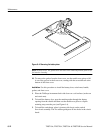
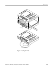
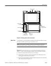
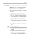
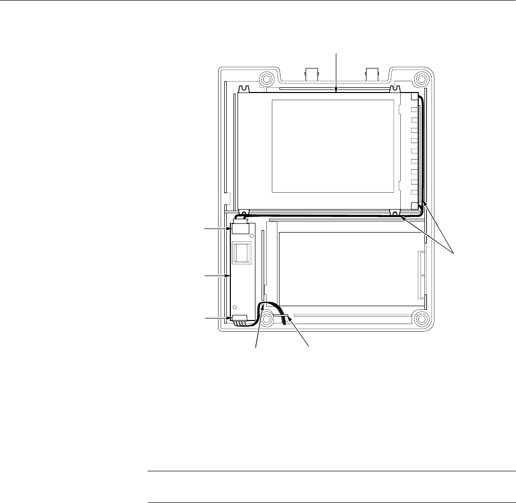
Route cable
through channels
Display module
Route cable
under clip
Route cable
through channel
Inverter input
connector
Inverter output
connector
Inverter board
Figure 6–10: Routing cables to the inverter board
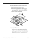
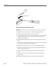
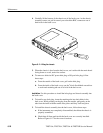
You will need a
1
@
8
inch flat-bladed screwdriver and needle-nose pliers to remove
the chassis assembly and hole plugs from the back cover.
NOTE. The back labels and battery contacts are an integral part of the back
cover. If any of these parts are defective, the back cover must be replaced.
Removal. First remove the front cover and switch mat using the procedure on
page 6–11. Then, use the following procedure to remove the chassis assembly.
1. Place the instrument back-side down on a soft surface.
2. Lift the battery connector, located on the handle-side of the chassis, off its
retaining pins and disconnect the connector.
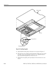
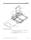
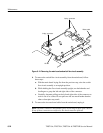
3. Insert the
1
@
8
inch flat-bladed screwdriver between the back cover and chassis
at the location shown in Figure 6–11.
Back Cover