Maintenance
THS710A, THS720A, THS730A & THS720P Service Manual
6–33
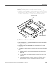
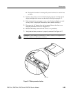
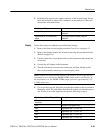
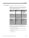
5. Hold the probe tip above the output connector of the inverter board. Do not
touch the probe tip to either of the conductors in the connector. Follow the
instructions in the table below.
Oscilloscope Display Instructions
No signal displayed The inverter board is probably defective.
Replace it.
Approximately 40 kHz sinewave dis-
played
The display module is probably defective.
Replace it.
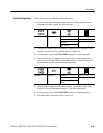
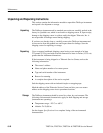
Follow these steps to troubleshoot a nonfunctional display.
1. Remove the front cover using the procedure Front Cover on page 6–11.
2. Remove the display module and inverter board using the procedure Display
Module on page 6–16.
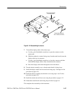
3. Fold the switch flex-circuit board back over the instrument and reinstall the
switch mat.
4. Connect the AC adapter to the instrument
5. Turn the instrument on, remove the switch mat, and then fold the switch
flex-circuit assembly toward you to access display cable.
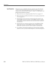
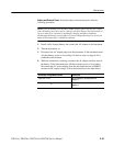
NOTE. Without the display module installed, the simplest way to verify that the
instrument is on is to probe the PROBE COMP output with an oscilloscope. If
the instrument is on, the PROBE COMP output generates approximately a 5 V,
1.2 kHz squarewave.
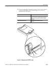
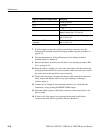
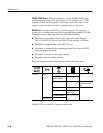
6. Use an oscilloscope and 10X probe to probe the contacts on the loose end of
the display cable. The table below describes the signals you should expect to
see. If some or all of the signals are not present, then skip to step 9.
Signal at Loose End of Display Cable Description
Pin 1 (closest to bottom of
instrument)
No signal, might appear noisy
Pin 2 No signal, might appear noisy
Pin 3 Digital data, high = 5 V, low = 0 V
Pin 4 Digital data, high = 5 V, low = 0 V
Pin 5 Digital data, high = 5 V, low = 0 V
Pin 6 Digital data, high = 5 V, low = 0 V
Display


