


Maintenance
6–16
THS710A, THS720A, THS730A & THS720P Service Manual
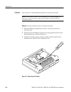
CAUTION. To avoid cross-threading or cutting new threads with the screws,
carefully follow the procedure in the next step.
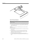
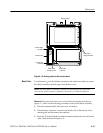
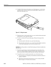
8. To install the four screws, follow these steps:
a. Place the screws into their holes in the back cover.
b. Using the torque-limiting Torx T-15 screwdriver, slowly turn each
screw backward (counterclockwise) until you feel the thread drop and
then gently tighten the screw (turn clockwise) into the existing thread.
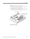
c. When all four all screws are in, hold a corner of the case together firmly
to compress the gasket while tightening its screw until snug. Repeat for
the other corners. Do not overtighten the screws (12 in ⋅ lbs or 1.m N ⋅ m
maximum torque).
9. Replace the battery as shown on page 2–2, and then close the battery door.
You will need a
1
@
8
inch flat-bladed screwdriver to remove the display module
and inverter board.
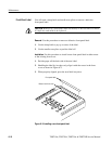
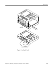
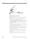
Removal. First remove the front cover and switch mat using the procedure on
page 6–11. Then, use the following procedure to remove the display module and
inverter board.
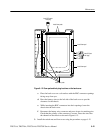
1. Fold the switch flex-circuit assembly toward you to expose the display
module and inverter board.
CAUTION. To avoid scratching the surface of the display module, do not let it
touch any hard object.
The display module surface may scratch easily. To clean it, first try pressurized
air. If a soft cloth is required to clean it, use very light pressure.
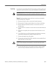
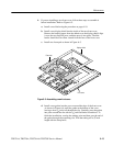
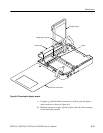
2. To remove the inverter board, unplug the input and output connectors and
then lift the inverter board off the two guideposts. You may want to use the
1
@
8
inch flat-bladed screwdriver to help release the connectors from their
sockets.
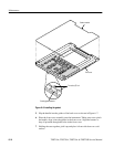
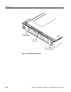
3. To remove the display module, follow these steps:
a. Disconnect the cable from the display module to the inverter board, if it
is not already disconnected.
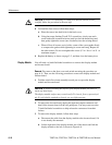
b. Lift the right side of the display module out of the chassis and fold the
display module to the left, as shown in Figure 6–8.
Display Module