


Maintenance
6–34
THS710A, THS720A, THS730A & THS720P Service Manual
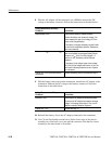
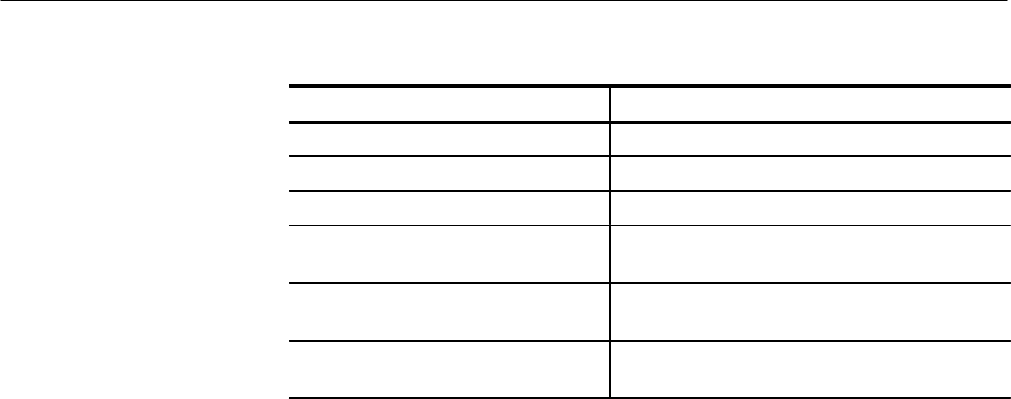
Signal at Loose End of Display Cable Description
Pin 7 –10 V
DC
to –22 V
DC
Pin 8 0 V (ground)
Pin 9 +5 V
DC
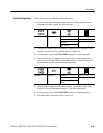
Pin 10 1.89 MHz clock (528 ns period), ≈ 50% duty cycle,
appears in bursts, high = 5 V, low = 0 V
Pin 11 19.3 kHz clock (51.7 ms period), ≈ 16% duty cycle,
high = 5 V, low = 0 V
Pin 12 (closest to BNC end of
instrument)
75.5 Hz clock (13.2 ms period), ≈ 0.4% duty cycle,
high = 5 V, low = 0 V
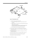
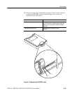
7. If all the signals are present on the loose end of the connector, turn the
instrument off and then reinstall the display module using the procedure on
page 6–18.
8. Turn the instrument on. If the problem persists, the display module is
probably defective. Replace it.
9. Remove the chassis assembly from the back cover using the procedure Back
Cover on page 6–19.
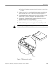
10. Place the chassis assembly on a soft, static-free surface with the main board
facing up and the switch flex-circuit assembly folded out toward you. Install
the switch mat on the switch flex-circuit assembly.
11. Check, and if necessary, reconnect the display cable connection to the main
board. Inspect the display cable for any sign of damage; if damage is
evident, replace it.
12. Connect the AC adapter to the instrument and turn it on. Verify that the
instrument is on by probing the PROBE COMP output.
13. Probe the display signals at the display connector of the main board as was
done in step 6.
14. If some or all of the signals are not present at the main board display
connector, the main board is probably defective. Replace it.