


Maintenance
6–20
THS710A, THS720A, THS730A & THS720P Service Manual
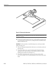
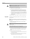
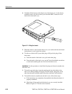
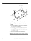
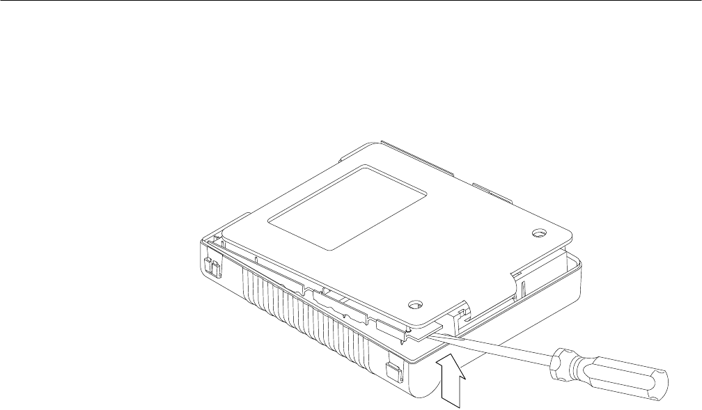
4. Carefully lift the bottom of the chassis out of the back cover. As the chassis
assembly comes out, pull it toward you to back the BNC connectors out of
their holes in the back cover.
Figure 6–11: Lifting the chassis
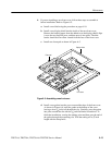
5. When the chassis is free from the back cover, set it aside with the main board
facing down on a soft, static-free surface.
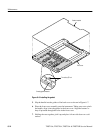
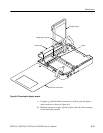
6. To remove a defective DC power hole plug or I/O port hole plug, follow
these steps:
a. From the outside of the back cover, pull on the hole plug.
b. From the inside of the back cover, use the
1
@
8
inch flat-bladed screwdriver
to work each retaining tab out of its hole in the back cover.
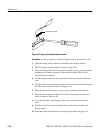
Installation. Use this procedure to install the hole plugs and chassis assembly into
the back cover.
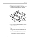
1. To install a new hole plug, insert the retaining tabs into their holes in the
back cover. While pushing on the plug from the outside, pull gently on the
tabs from the inside with the needle-nose pliers until they lock into place.
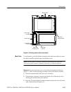
2. To install the chassis assembly into the back cover, follow these steps:
a. If the instrument was completely disassembled, check that the chassis is
properly assembled.
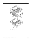
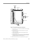
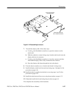
b. Check that all foam pads inside the back cover are correctly installed.
Refer to Figure 6–12 for the correct locations.