


Specifications
1–6
THS710A, THS720A, THS730A & THS720P Service Manual
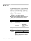
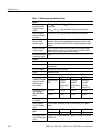
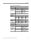
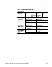
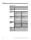
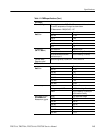
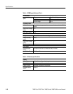
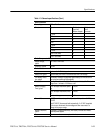
Table 1–1: Oscilloscope specifications (Cont.)
Power Measurements (THS720P)
PF Measurement
Power factor (PF) +
true power
apparent power
+
W
VA
q Measurement q is the phase difference between the fundamental components of
voltage and current. Positive angle means voltage leads current.
Negative angle means voltage lags current.
DPF Measurement Displacement power factor (DPF) = cos q
Power Factor Mea-
surements Accuracy
±0.05
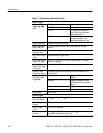
With P6117 Probe
A
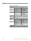
nalog Ban
d
wi
d
th,
DC C p ed
THS710A THS720A THS720P THS730A
DC
C
ou
p
l
ed
60 MHz 100 MHz
(90 MHz above
35° C)
100 MHz
(90 MHz above
35° C)
200 MHz
(180 MHz
above 35° C)
Probe Attenuation 10X
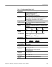
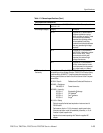
Maxi
m
u
m
Voltag
e
eee rbeTp
Overvoltage Category Maximum Voltage
B
e
tw
ee
n P
r
o
be
T
i
p
and Reference Lead
CAT II Environment (refer to
page 1–13)
300 V
RMS
CAT III Environment (refer to
page 1–13)
150 V
RMS
For steady-state sinusoidal waveforms, derate at 20 dB/decade above
900 kHz to 13 V
pk
at 27 MHz and above. Also, refer to Overvoltage
Category description on page 1–13.
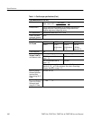
Maximum Voltage
Between Reference
Lead and Earth
Ground Using P6117
Probe
30 V
RMS
, 42.4 V
pk
Maximum Voltage,
Channel-to-Channel
Reference Leads
Using P6117 Probe
30 V
RMS
, 42.4 V
pk