


Adjustment Procedures
5–8
THS710A, THS720A, THS730A & THS720P Service Manual
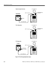
Meter Adjustment
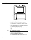
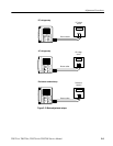
Three equipment setups, shown in Figure 5–3, are required to complete this
adjustment procedure. For each step in the procedure, the specific input signal
required by that step is described in the TekScope instrument display. Refer to
these diagrams as necessary during the procedure. Table 5–2 summarizes the
steps in the procedure and the signal requirement for each step.
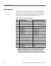
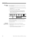
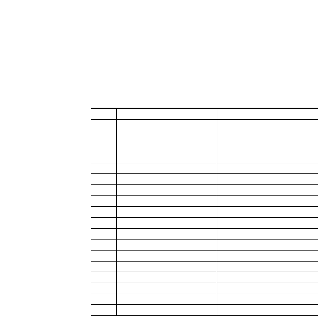
Table 5–2: Summary of meter adjustment steps
Step Uses Equipment Setup Signal or Resistance Source Setting
1 DC voltage setup +400.0 mV
2 DC voltage setup 4.000 V
3 DC voltage setup 40.00 V
4 DC voltage setup 400.0 V
5 DC voltage setup 850.0 V
6 AC voltage setup 400.0 mV
RMS
, 500 Hz
7 AC voltage setup 4.000 V
RMS
, 500 Hz
8 AC voltage setup 40.00 V
RMS
, 500 Hz
9 AC voltage setup 400.0 V
RMS
, 500 Hz
10 AC voltage setup 600.0 V
RMS
, 500 Hz
11 Resistance standard setup 100.0 W
12 Resistance standard setup 1.000 kW
13 Resistance standard setup 10.00 kW
14 Resistance standard setup 100.0 kW
15 Resistance standard setup 1.000 MW
16 Resistance standard setup 10.00 MW
17 DC voltage setup
1
500.0 mV
18 DC voltage setup
1
1.000 V
1
In steps 17 and 18, the DC voltage source must be able to sink approximately 1 mA
supplied by the TekScope instrument. You must determine whether or not your DC
voltage source is capable of sinking current supplied by a device under test. If the
DC voltage source cannot sink current, you can connect a 470 W,
1
?
8
W shunt
resistor across the output of the DC voltage source during steps 17 and 18 only. The
shunt resistor will accommodate the current supplied by the TekScope instrument.