Adjustment Procedures
THS710A, THS720A, THS730A & THS720P Service Manual
5–5
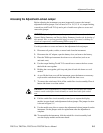
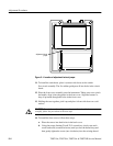
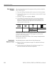
c. When all four all screws are in, hold a corner of the case together firmly
to compress the gasket while tightening its screw until snug. Repeat for
the other corners. Do not overtighten the screws (14 in ⋅ lbs or 1.5 N ⋅ m
maximum torque).
15. Replace the battery as shown on page 2–2, and then close the battery door.
Oscilloscope Adjustment
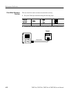
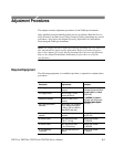
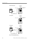
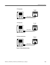
Three equipment setups, shown in Figure 5–2, are required to complete this
adjustment procedure. For each step in the procedure, the specific input signal
required by that step is described in the TekScope instrument display. Refer to
these diagrams as necessary during the procedure. Table 5–1 summarizes the
steps in the procedure and the signal requirement for each step.
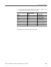
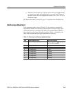
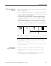
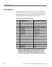
Table 5–1: Summary of oscilloscope adjustment steps
Step Uses Equipment Setup Signal Source Setting
1 Square wave generator setup Fast rise output, 300 mV
p-p
amplitude,
500 Hz or 950 Hz frequency
2 Zero voltage setup None
5 DC voltage setup +7.000 V
6 DC voltage setup –7.000 V
7 DC voltage setup +700.0 mV
8 DC voltage setup –700.0 mV
9 DC voltage setup +70.00 mV
10 DC voltage setup –70.00 mV


