THS710A, THS720A, THS730A & THS720P Service Manual
5–1
Adjustment Procedures
This chapter contains adjustment procedures for the TekScope instrument.
Only qualified personnel should perform service procedures. Read this Service
Safety Summary and the General Safety Summary before performing any service
procedures. Also refer to the chapter Operating Information for information
about using the TekScope instrument.
NOTE. The voltage references inside the TekScope instrument are very stable over
time and should not require routine adjustment. Before performing any proce-
dure in this chapter, first verify that the instrument does not meet specifications.
Refer to the chapter Performance Verification for procedures to verify the
specifications.
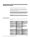
Required Equipment
The following equipment, or a suitable equivalent, is required to complete these
procedures.
Description
Minimum
Requirements
Examples
DC Voltage Source 400 mV to 800 V, ±0.1%
accuracy
W
av
e
t
e
k
9100
U
niv
ers
al
Calibration System with Oscil-
speCbr de
AC Voltage Source 400 mV to 600 V, ±0.5%
accuracy at 500 Hz
lo
s
co
pe
C
ali
br
ation Mo
d
ul
e
(Option 250)
F e 5500A -pr d
Resistance Standard 100 W to 10 MW, ±0.1%
accuracy
F
luk
e
5500A
Multi
-pr
o
d
uct
Calibrator with Oscilloscope
C
ali
br
ation
Op
tion (
Op
tion
Fast-Rise Square Wave
Generator
300 mV step, ≤20 ns risetime,
≤0.5% flattness from 500 ns
to 200 ms, 500 Hz or 950 Hz,
nominal 50% duty cycle
C
ali
br
ation
Op
tion (
Op
tion
5500A-SC)
Banana to Banana Cable (two
required)
Shielded banana jacks on
each end
Tektronix Deluxe Meter Lead
Set (ATLDX1)
50 W BNC Cable BNC male to BNC male,
≈ 36 in (1 m) long
Tektronix part number
012-0482-00
50 W BNC Cable BNC male to BNC male,
≈ 10 in (25 cm) long
Tektronix part number
012-0208-00
50 W Feedthrough
Termination
BNC male and female con-
nectors
Tektronix part number
011-0049-01


