


Maintenance Model 7500ZA
Teledyne Analytical Instruments 80
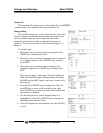
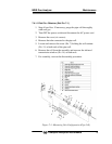
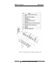
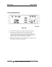
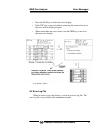
7.4.1.2 BLOCK CELL REMOVAL (SEE FIG. 7-2)
For steps 1 to 4, see 7.4.1.1, Pipe Cell Removal.
5. Disconnect and remove detector output cables from detector
output circuit board (No.12). Applying identification mark on
top of removed cable connector will ensure proper pin
assignment later.
6. Unscrew the two screws (No. 10) that hold the detector to the
light source unit to remove the detector from the measuring unit.
The block cell can be removed together with the detector.
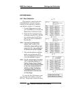
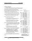
7. To remove the block cell, unscrew the two screws (No. 6)
holding the block cell to the detector. The infrared transmission
window (No. 8) is just sandwiched (not fixed) between the
detector and block cell. Keep the detector facing up, when
removing this window.
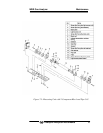
8. For assembly, reverse the disassembly procedures.
Note: The O-ring (No. 9) is placed between the window holder
and block cell. Use care in positioning the O-ring. With a
two-component analyzer, install the two-component
detector last. Make sure that no space is left between the
one-component and two-component detectors. When
inserting the detector output cable connector into the PCB
board, be careful to attach the connector with proper pin
assignment (top/bottom).