


Maintenance Model 7500ZA
Teledyne Analytical Instruments 82
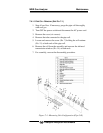
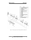
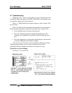
7.4.1.3 REMOVING THE MEASURING UNIT
Refer to Fig. 7-3. For step 1 to 4, see 7.4.1.1, Pipe Cell Removal.
5. Disconnect and remove detector output cables from detector
output circuit board (No.12). Applying identification mark on
top of removed cable connector will ensure proper pin
assignment later.
6. Disconnect wiring to the 2-pin terminals of the IR light source
assembly and chopper motor pin connector from the PCB (No. 17).
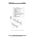
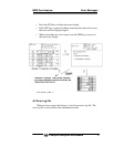
7. Detach the six screws (No. 16) fastening the base plate (No. 3) to
remove the measuring unit. .
8. For assembly, reverse the disassembly procedures.
Note: Special care should be taken when assembling or
disassembling the measuring cell to avoid using excessive
force to the detector pipe or light source unit pipe. If the pipe
is deformed or damaged by excessive force, there is a
potential for gas leaks and this, in addition to creating a
potential toxic hazard, will result in inaccurate measurement.
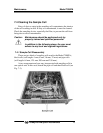
7.4.2 Cleaning the Sample Cell
1. To clean the sample cell or IR transmission window, first clear
away any dirt using a soft brush and then lightly wipe using a
soft cloth. Do not use abrasive or paper towels.
Note: The window is fragile. Handle with care. Avoid scratching
the window. Do not rub the dirt from the window roughly.
2. If the window or the sample cell interior is very dirty, use a soft
line-free cloth moistened with absolute alcohol.
3. If the window is corroded, rub off any scale from the window
lightly with a soft cloth to which chrome oxide powder is
applied. If it is excessively corroded, it should be replaced.
4. When the cleaning operation is complete, assemble according to
the sample cell assembly/disassembly procedures. Assemble the
pipe carefully. If it becomes bent or damaged, replace it with a
new part.
5. Do not wash the sample cell components with water.