


GE864 Hardware User Guide
1vv0300694 Rev.10 - 10/06/08
Reproduction forbidden without Telit Communications S.p.A. written authorization - All Rights Reserved page 21 of 69
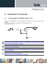
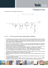
An example of linear regulator with 5V input is:
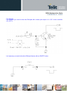
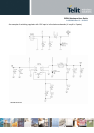
5.2.1.2 + 12V input Source Power Supply Design Guidelines
• The desired output for the power supply is 3.8V; hence due to the big difference between the input
source and the desired output, a linear regulator is not suited and shall not be used. A switching
power supply will be preferable because of its better efficiency especially with the 2A peak current
load represented by the GE864-QUAD/PY.
• When using a switching regulator, a 500kHz or more switching frequency regulator is preferable
because of its smaller inductor size and its faster transient response. This allows the regulator to
respond quickly to the current peaks absorption.
• In any case the frequency and Switching design selection is related to the application to be
developed due to the fact the switching frequency could also generate EMC interferences.
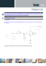
• For car PB battery the input voltage can rise up to 15,8V and this should be kept in mind when
choosing components: all components in the power supply must withstand this voltage.
• A Bypass low ESR capacitor of adequate capacity must be provided in order to cut the current
absorption peaks, a 100μF tantalum capacitor is usually suited.
• Make sure the low ESR capacitor on the power supply output (usually a tantalum one) is rated at
least 10V.
• For Car applications a spike protection diode should be inserted close to the power input, in order
to clean the supply from spikes.
• A protection diode should be inserted close to the power input, in order to save the GE864-
QUAD/PY from power polarity inversion. This can be the same diode as for spike protection.