


GE864 Hardware User Guide
1vv0300694 Rev.10 - 10/06/08
Reproduction forbidden without Telit Communications S.p.A. written authorization - All Rights Reserved page 57 of 69
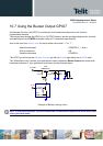
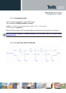
11.2 ADC Converter
11.2.1 Description
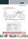
The on board A/D are 11-bit converter. They are able to read a voltage level in the range of 0÷2 volts
applied on the ADC pin input, store and convert it into 11 bit word.
Min Max Units
Input Voltage range 0 2 Volt
AD conversion - 11 bits
Resolution - < 1 mV
The GE864-QUAD / PY module provides 3 Analog to Digital Converters. The input lines are:
ADC_IN1 available on Ball J11 and Pin 19 of PL102 on EVK2 Board (CS1152).
ADC_IN2 available on Ball H11 and Pin 20 of PL102 on EVK2 Board (CS1152).
ADC_IN3 available on Ball G11 and Pin 21 of PL102 on EVK2 Board (CS1152).
11.2.2 Using ADC Converter
An AT command is available to use the ADC function.
The command is AT#ADC=1,2
The read value is expressed in mV
Refer to SW User Guide or AT Commands Reference Guide for the full description of this function.