


GE864 Hardware User Guide
1vv0300694 Rev.10 - 10/06/08
Reproduction forbidden without Telit Communications S.p.A. written authorization - All Rights Reserved page 49 of 69
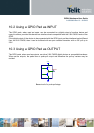
10.7 Using the Buzzer Output GPIO7
As Alternate Function, the GPIO7 is controlled by the firmware that depends on the function
implemented internally.
This setup places always the GPIO7 pin in OUTPUT direction and the corresponding function must be
activated properly by AT#SRP command (refer to AT commands specification).
Also in this case, the dummy value for the pin state can be both “0” or “1”.
Send the command AT#GPIO=7, 1, 2<cr>:
Wait for response OK
Send the command AT#SRP=3
The GPIO7 pin will be set as Alternate Function pin with its dummy logic status set to HIGH value.
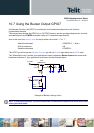
The "Alternate function” permits your application to easily implement Buzzer feature with some small
hardware extension of your application as shown in the next sample figure.
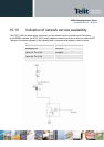
Example of Buzzer’s driving circuit.
NOTE: To correctly drive a buzzer, a driver must be provided; its characteristics depend on the Buzzer and for them
refer to your buzzer vendor.
TR1
BCR141W
TR2
SMBT2907A
R1
4,7K
R2
1K
D1
D1N4148
C1
33pF
+
-
+V buzzer
GPIO7