


GE864 Hardware User Guide
1vv0300694 Rev.10 - 10/06/08
Reproduction forbidden without Telit Communications S.p.A. written authorization - All Rights Reserved page 38 of 69
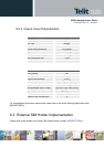
NOTE: The UART input line TXD (rx_uart) of the GE864-QUAD / PY is NOT internally pulled up with a resistor, so
there may be the need to place an external 47KΩ pull-up resistor, either the DTR (dtr_uart) and RTS (rts_uart) input
lines are not pulled up internally, so an external pull-up resistor of 47KΩ may be required.
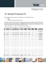
A power source of the internal interface voltage corresponding to the 2.8VCMOS high level is
available at the VAUX pin on the connector,
A maximum of 9 resistors of 47 KΩ pull-up can be connected to the PWRMON pin, provided no other
devices are connected to it and the pulled-up lines are GE864-QUAD / PY input lines connected to
open collector outputs in order to avoid latch-up problems on the GE864-QUAD / PY.
Care must be taken to avoid latch-up on the GE864-QUAD / PY and the use of this output line to
power electronic devices shall be avoided, especially for devices that generate spikes and noise such
as switching level translators, micro controllers, failure in any of these condition can severely
compromise the GE864-QUAD / PY functionality.
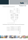
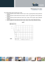
NOTE: The input lines working at 2.8VCMOS can be pulled-up with 47KΩ resistors that can be connected directly to
the VAUX line provided they are connected as in this example.
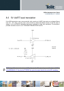
In case of reprogramming of the module has to be considered the use of the RESET line to start correctly the
activity.
The preferable configuration is having an external supply for the buffer.