


GE864 Hardware User Guide
1vv0300694 Rev.10 - 10/06/08
Reproduction forbidden without Telit Communications S.p.A. written authorization - All Rights Reserved page 51 of 69
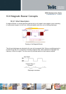
10.8.2 Frequency Behaviour
The frequency behavior represents the effectiveness of the reproduction of the applied signals.
Because its performance is related to a square driving waveform (whose amplitude varies from
0V to Vpp), if you modify the waveform (e.g. from square to sinus) the frequency response will
change.
10.8.3 Power Supply Influence
Applying a signal whose amplitude is different from that suggested by manufacturer, the
performance change following the rule “if resonance frequency f
o
increases, amplitude
decreases”.
Because of resonance frequency depends from acoustic design, lowering the amplitude of the
driving signal the response bandwidth tends to become narrow, and vice versa.
Summarizing: Vpp ↑
Æ
f
o
↓ Vpp ↓
Æ
f
o
↑
The risk is that the f
o
could easily fall outside of new bandwidth; consequently the SPL could
be much lower than the expected.
10.8.4 Warning
It is very important to respect the sense of the applied voltage: never apply to the "-" pin a
voltage more positive than "+" pin : if this happens, the diaphragm vibrates in the opposite
sense with a high probability to be expelled from its physical position , damaging the device
forever .
10.8.5 Working Current Influence
In the component data sheet you will find the value of MAX CURRENT : this represents the
maximum average current that can flow at nominal voltage without current limitation .
In other words it is not the peak current, which could be twice or three times higher.
If driving circuitry does not support these peak values , the SPL will never reach the declared
level or the oscillations will stop.