


GE864 Hardware User Guide
1vv0300694 Rev.10 - 10/06/08
Reproduction forbidden without Telit Communications S.p.A. written authorization - All Rights Reserved page 34 of 69
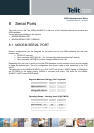
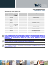
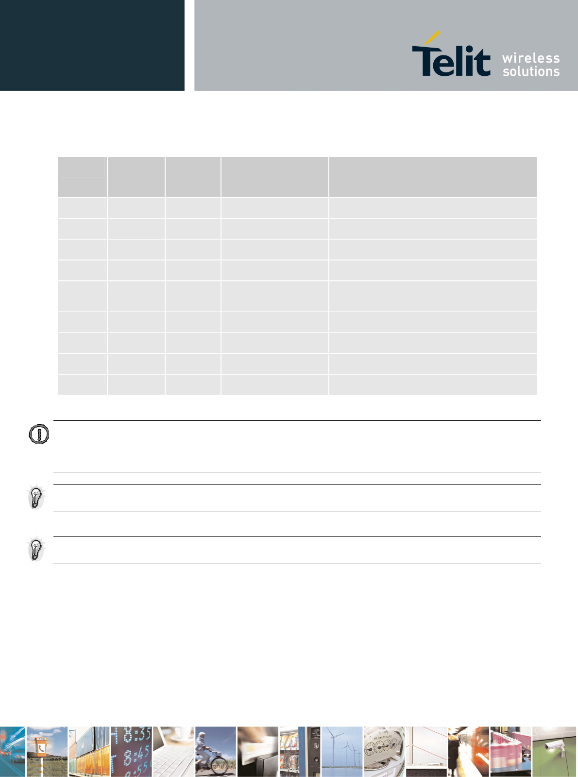
The signals of the GE864 serial port are:
RS232 Pin
Number
Signal GE864-
QUAD / PY
Pad
Number
Name Usage
1 DCD –
dcd_uart
D9 Data Carrier Detect Output from the GE864-QUAD / PY that indicates
the carrier presence
2 RXD –
tx_uart
H8 Transmit line *see Note Output transmit line of GE864-QUAD / PY UART
3 TXD –
rx_uart
E7 Receive line *see Note Input receive of the GE864-QUAD / PY UART
4 DTR –
dtr_uart
B7 Data Terminal Ready Input to the GE864-QUAD / PY that controls the
DTE READY condition
5 GND A1,F1,H1,L1
, H2, L2, J3,
K3….
Ground ground
6 DSR –
dsr_uart
E11 Data Set Ready Output from the GE864-QUAD / PY that indicates
the module is ready
7 RTS –
rts_uart
F7 Request to Send Input to the GE864-QUAD / PY that controls the
Hardware flow control
8 CTS –
cts_uart
F6 Clear to Send Output from the GE864-QUAD / PY that controls
the Hardware flow control
9 RI – ri_uart B6 Ring Indicator Output from the GE864-QUAD / PY that indicates
the incoming call condition
NOTE: According to V.24, RX/TX signal names are referred to the application side, therefore on
the GE864 side these signal are on the opposite direction: TXD on the application side will be
connected to the receive line (here named TXD/ rx_uart ) of the GE864 serial port and
viceversa for RX.
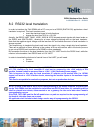
TIP: For a minimum implementation, only the TXD and RXD lines can be connected, the other
lines can be left open provided a software flow control is implemented.
TIP: In order to avoid noise or interferences on the RXD lines it is suggested to add a pull up
resistor (100Kohm to 2.8V)