


Workman 200 Ultra Sonic Boom System (Rev. C)Page 3.2 -- 19
Retrieving Fault Codes
All Ultra Sonic Boom System fault codes are retained in
the TEC controller memory. The three (3) most recent
fault codes that have occurred within the last forty (40)
hours of operation can be retrieved using the diagnostic
lamp. To retrieve these fault codes from the controller
memory, perform the following steps:
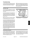
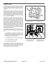
1. Make sure that ignition switch is OFF.
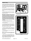
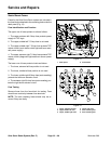
2. Locate diagnostic tether cap that connects the two
(2) diagnostic shunt wires located near the TEC control-
ler on the mounting plate under the dash panel (Fig. 9).
3. Remove diagnostic tether cap from diagnostic shunt
wires and connect the two (2) shunt wires together.
4. Turn ignition switch to the ON position.
5. Monitor the diagnostic lamp for fault code(s).
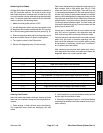
Faultcodes displayedb y thediagnostic lampa re two(2)
digit numbers with no digit larger than five (5). Fault
codes are listed in the chart below. There will be a one
(1) second pause between the first and second digit of
a code. Up to three (3) fault codes retained in controller
memorywill bedisplayedbythe diagnosticlampin order
from the most recent fault to the oldest fault. If there are
multiple faults in controller memory, there will be a three
(3) second pause between codes. The fault codes will
continually repeat after a five (5) second pause until the
ignition key is turned OFF.
If there are no faults that have occurred within the last
forty (40) hours of operation, the diagnostic lamp will
flash continuously after performing the above steps.
If afaultcode isnot retrievedfrom the controllermemory
within forty (40) hours of machine operating time, the
fault cannot be r etrieved from controller memory using
this procedure. If necessary, contact your Toro distribu-
tor to retrieve older fault codes.
After necessary service has been performed, discon-
nect diagnostic shunt wires and insert shunt leads into
diagnostic tether cap. Lower operator seat.
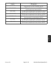
Fault Code (Lamp Flashes)
Fault Description
1--2 Left sonic boom sensor fault occurred
1--3 Right sonic boom sensor fault occurred
1--6 TEC inputs are out of range (sonic boom operation will stop)
2--1 Theextremeright7.5Ampfuseinboomsupplyfuseblockisfaulty
2--2 The middle right 7.5 Amp fuse in boom supply fuse block is faulty
2--3 The middle left 7.5 Amp fuse in boom supply fuse block is faulty
2--4 Main electrical power to sonic boom system was interrupted
3--4 Left boom raise function (output) is grounded or faulty
4--1 Right boom raise function (output) is grounded or faulty
4--2 Right boom lower function (output) is grounded or faulty
4--5 Left boom lower function (output) is grounded or faulty
Clearing Fault Codes
After fault codes have been retrieved, clearing of those
faults can be completed using the following switch se-
quence:
1. Place sprayer in fault retrieval mode (see above).
The diagnostic lamp should be displaying the fault
codes.
2. At thesame time, press the left boom switch to lower
and the right boom switch to raise.
3. Monitor the diagnostic lamp for continuous flashing
indicating that all faults have been cleared from the con-
troller memory.
Ultra Sonic
Boom System