Rev. B
Workman 200 Spray SystemPage 3.1 -- 18Sonic Boom System (Optional Kit)
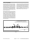
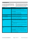
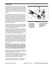
Diagnostic Display
Inputs
Diagnostic Display
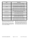
LED Operation
AUTO MODE Sonic mode switch in auto position: LED ON
Sonic mode switch not in auto position: LED OFF
L RAISE Left boom actuator switch in raise position: LED ON
Left boom actuator switch not in raise position: LED OFF
LLOWER Left boom actuator switch in lower position: LED ON
Left boom actuator switch not in lower position: LED OFF
R RAISE Right boom actuator switch in raise position: LED ON
Right boom actuator switch not in raise position: LED OFF
RLOWER Right boom actuator switch in lower position: LED ON
Right boom actuator switch not in lower position: LED OFF
LNOSNSRDATA ECU has detected an invalid reading from left sensor: LED ON
Left sensor operating normally: LED OFF
L NOT TRACKING Left boom not tracking to target within 5 seconds: LED ON
Left sensor operating normally: LED OFF
RNOSNSRDATA ECU has detected an invalid reading from right sensor: LED ON
Right sensor operating normally: LED OFF
R NOT TRACKING Right boom not tracking to target within 5 seconds: LED ON
Right sensor operating normally: LED OFF
L -- SNSR FEEDBACK ECU receiving signal from left sensor: LED ON
ECU not receiving signal from left sensor: LED OFF
R -- SNSR FEEDBACK ECU receiving signal from right sensor: LED ON
ECU not receiving signal from right sensor: LED OFF
NOTE: When the vehicle ignition switch is in the OFF
position, all Diagnostic Display LED’s should be OFF.
NOTE: Initial calibration of the Sonic Boom sensors is
required for proper operation of ECU inputs. Refer to
your Sonic Boom Kit Installation Instructions for infor-
mation on initial sensor calibration.
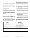
NOTE: Right and left side Sonic Boom sensors are
identical so they can be exchanged to assist in trouble-
shooting. Ifa problem followsthe exchangedsensor, an
electrical problem likely exists with the sensor. If the
problem remains unchanged, something other than the
sensoris theproblemsource(e.g.switch, circuitwiring).


