


42
Plast Coat 430
GB
6 COMMISSIONING
6.1 INSTALLATION LOCATION
Themortarsprayingmachineandthebucketfromwhichthe
material to be processed is to be pumped have to be set up on
an even and rm underground. This ensures that the machine
andbucketcannotslideawayorfallover.
6.2 INITIAL STARTINGUP
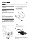
6.2.1 SCOPE OF SUPPLY
Themachineissuppliedbythemanufacturerinthefollowing
individual components:
• Completebasicmachinecomprisingdriveunit,controlunit
and transport frame with wheels
• Pump unit complete
• Tool:Specialkey
• Hose package
• Spraylance
• Pump sliding means
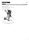
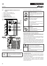
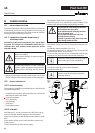
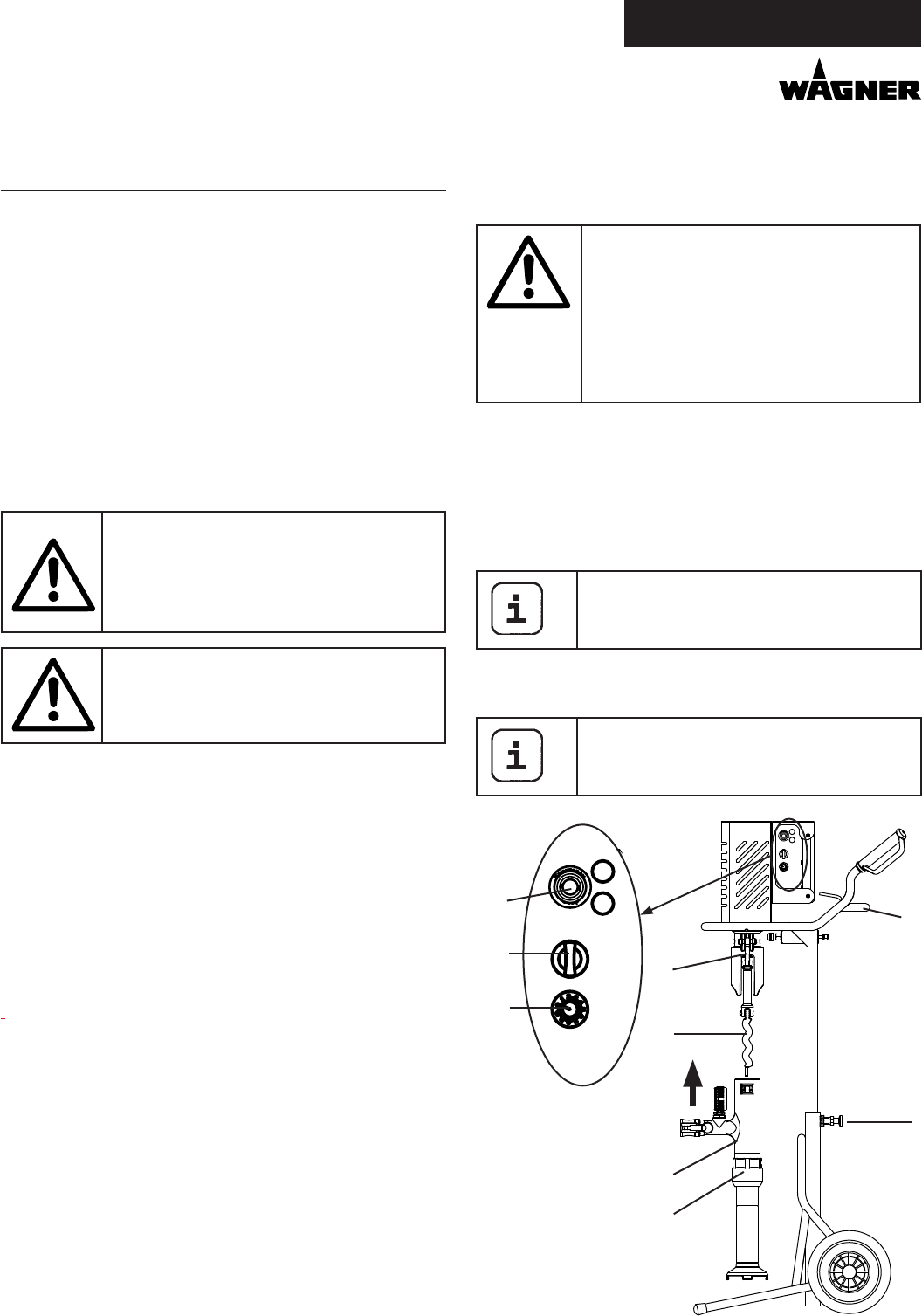
6.2.2 ASSEMBLY
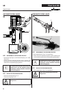
Pullsafetypin(1)toreartoreleaselock.PullPC430upbyits
frame (2) until the machine engages in the top position.
Sprayrotor(3)withasuitablepumplubricant(orderno.9992
824).
Moveselectorswitch(4)to“A”andsetdeliveryvolumecon-
troller (5) to „0“.
Connectmainsplugtomainspowersupply.
commIssIonIng
• Beforeconnectingtheunittothemainssupply,ensurethat
the line voltage matches that specied on the rating plate.
Min. wire cross-section 3 x 1.5 mm
2
. Unroll the
extension cable completely. Ensure that the
coupling pieces and plugs are free of dam-
age.
Laythedevicesupplycablesothatthereisno
danger of stumbling.
Protect against damage, for example against
being driven over.
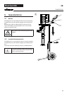
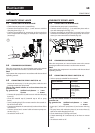
6.1.1 CONNECTION TO MAINS POWER SUPPLY/
EXTENSION CABLE
Connection to the mains network only via a special feed-
ing point, for example via a distribution board for con-
struction sites, with residual current protective device
with INF ≤ 30 mA.
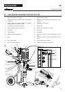
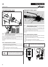
The operation light (6) shows operational readiness.
Fold locking pins (7) up towards the magnet holders in the
handletopreventthembeingtwistedduringassembly.
Only the person controlling the machine
may assemble the pump unit.
Never operate mortar spraying machine
with an exposed rotor.
Do not reach into the rotor when it is
moving. Risk of crushing.
Caution if you have long hair. Only wear
close-tting clothes at work.
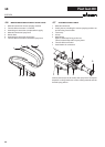
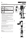
Slide pump unit (8) over rotor (3) from below and press up-
wards.
Setdeliveryvolumecontroller(5)to1or2.
Set selector switch (4) to “F” to switch on pump. The pump unit
isautomaticallydrawnupbytherotor.
As soon as the pump unit is in its end position, fold the two
locking pins (7) down and use nuts to x the pump unit.
Ifnecessaryrotatepumpunit(8)byhandto
move locking pins (7) into end position.
Set selector switch (4) to “A” to switch o pump.
Disconnect mains plug.
After assembling the pump unit, secure the
union nut (9) on the pump unit, using the
specialkeytodoso.
A
F R
POWER
ERROR
4
6
2
1
3
A
F
R
POWER
ERROR
5
7
8
9