


38
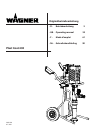
Plast Coat 430
GB
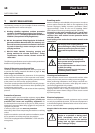
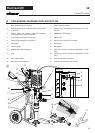
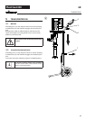
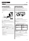
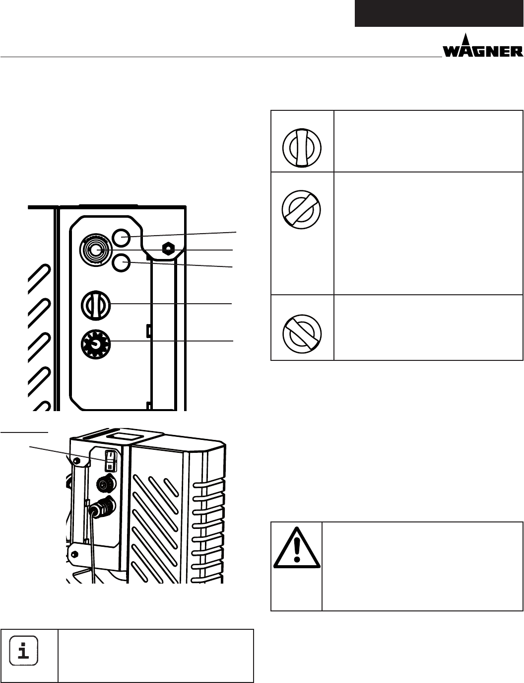
4.1 OPERATING ELEMENTS AND DISPLAYS ON
DEVICE
1 Deliveryvolumecontroller 0-10
2 Selector switch for operating mode
3 Indicator light (Error)
4 Operating light (Power)
5 EMERGENCY STOP switch
6 Switch for activating remote control
Thedeliveryvolumecontroller(Fig. 3, 1) is used to regulate
theconveycapacityfrom0-10smoothly.
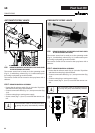
Theremotecontrol(availableseparately,art.
no.2308417)canbeusedtoconveniently
controlthepump‘sdeliveryvolumefromthe
spraylance.
overvIew
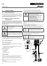
The selector switch (Fig. 3, 2) oers the following modes:
A
R
F
“A” position = automatic
Basic setting for control with an automatic
spraylance,pneumaticspraylanceorre-
mote control
A
R
F
“F” position = manual activation
Switchesonthemortarsprayingmachine.
This setting is required for:
• suctionunitassembly
When using the pneumatic lance, this set-
ting is also needed for:
• pre-rinsing the mortar hose to improve
thematerial‘sabilitytoslide
• cleaning
A
R
F
“R” position = reverse gear (must be held in
this position).
This setting is required for:
• relievingpressureonthemortarhose
• suctionunitdisassembly
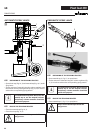
Detailed explanation of selector switch use:
If the selector switch is in the “A” position, the PC430 can be
switched on and o with the material shut-o on the auto-
maticorpneumaticspraylance.
Ifthereisnospraylancetted(e.g.:assembly/disassemblyof
suction unit), the machine is switched on using the “F” switch
position and o using the “A” position.
Since the air supply through the compressor needs to be
switched o to clean the mortar hose, the pneumatic lance
is not controlled using the material shut-o. In this case, the
machine must therefore also be switched on using the “F” po-
sition.
Important: control via the selector switch and
materialshut-oaretreatedequally.
The machine can be switched from the “A” po-
sition (control using material shut-o) to “F” at
anytime.
Wewouldthereforerecommendthatonlyone
person operate the machine.
The operating light (green, Fig. 3, 4) indicates that the machine
isenergisedandready.
The indicator light (red, Fig. 3, 3) indicates a fault. For detailed
information about this kind of fault, refer to the „Rectication
of faults“ section on page 50.
The switch(Fig.3, 6)allowsyou toswitchbetweeninternal
and external control. In Position “I“, the PC 430 is controlled
with the integrated control panel. In Position “II” it is controlled
with the remote control.
2
A
F R
POWER
ERROR
1
4
3
Rear view
6
5