


3-07
Solution Spray Control System (Optional)
See the controller manufacturer’s manual for operation
instructions.
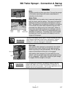
Light and Marking System
The light system on the sprayer works with the tractor’s
light system. Amber lights flash in unison with the tractor
amber flashing lights. If a turn is not being signaled, both
amber lights flash. When the operator signals a right turn
with the tractor’s turn signal switch, the left amber light
stops flashing and remains on and the right amber flash-
es at the same flashing rate as the tractor’s right amber
turn light. If a left turn is signaled, the opposite takes
place.
Red taillights also follow the tractor lights in their function.
If road lights are on and the taillights of the tractor are lit,
the red taillights will be lit on the implement. In a turn, the
red, high intensity portion of the taillight will come on. As
with the amber, in a right turn the left red, high intensity
portion of the taillight will remain on and the right taillight
flashes at the same rate as the tractor’s red turn signal
light. If a left turn signal is turned on, the opposite takes
place. In a turn situation, this lighting system produces
the effect of a vehicle braking and turning in the direction
of the flashing light. The turn signal module, "The Black
Box", produces the turn signal/stop effect with the red
lights. See Section F for the location of this module.
The light and marking system also incorporates reflective
decals front and rear of proper size and location for night
travel and fluorescent decals of proper size and location
for daylight travel.
Foam Marker (Optional)
Refer to the foam marker manual for operational
instructions.
565 Trailer Sprayer - Operation Instructions
Section B
12
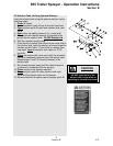
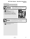
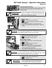
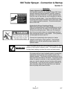
Section B
Lights and Rear Facing Reflective and
Florescent Decals