


3-07
7
Section C
565 Trailer Sprayer - Connection & Startup
Section C
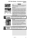
It has a set of hoses leading from the hydraulic valve bank
to the tractor hydraulics connecting with a pair of hydraulic
hoses with quick couplers. The operator needs to actuate
the tractor hydraulic controls for the valve the hydraulic con-
troller connects first, then actuate the toggle switch on the
hydraulic controller's switch box for the function needed.
The hydraulic controller could operate three sets of sole-
noids at one time allowing hydraulic oil out of both valve
bank ports at the same time provided the tractor can supply
enough hydraulic flow to operate three circuits at once.
When the action is complete, the operator will release the
toggle switch on the controller switch box and return the
tractor hydraulic lever or switch to the neutral position.
The hydraulic controller also has the provision for a foam
marker activation with a fourth 3-position switch in the
switch box. The center position is off and moving the toggle
to one side or the other will operate the foam marker for one
side or the other of the sprayer.
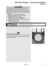
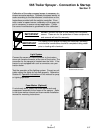
Boom fold control switch needs to be wired into the cab.
Redball
®
provides a harness that needs to be routed from
the hitch area into the cab. This is then connected to the
boom control switch box provided. A power source of 12V
DC and a chassis ground capable of 15 amps is required for
this panel. The wire with the inline fuse is positive.
Solution S
pray Control System (Optional)
Install the solution spray control console in the cab and
route the wire harness to the back of the tractor per installa-
tion instructions provided by the control manufacturer.
Install the speed sensor or radar (if necessary) and connect
them to the solution controller according to the speed sen-
sor, radar and solution controller manufacturer’s instruc-
tions. For tractors with radar systems built in, interface
cables are available from your Redball
®
Dealer.
Correct connection of the radar, speed sensor, flow meter,
control valve to the console should be made according to
control manufacturer’s instructions.
DO NOT remove the fuse or fuse holder from this power
source. These are for the protection of these components
and removal will void the warranty.
IMPORTANT