


3-07
565 Trailer Sprayer - Connection & Startup
Section C
8
Section C
Calibration of the radar or speed sensor is necessary to
ensure accurate readings. Calibrate the speed sensor or
radar according to the manufacturer’s instructions or the
instructions provided with the solution controller. Even
with a radar or speed sensor, calibration of the spray out-
put is necessary to assure correct application. Follow
the control manufacturer’s guidelines for this calibration.
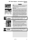
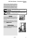
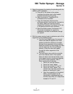
Light System
Connect the seven-pin male connector to the tractors
seven-pin female connector at the rear of the tractor. The
connector for the sprayer is located near the hitch. If the
tractor is not equipped with such a connector, see your
tractor dealer.
Test the operation of the lighting system. Correct any sit-
uation where the lights do not work properly. Reference
Section B, Operation Instructions
of this manual for prop-
er lighting operation.
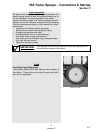
Foam Marker (Optional)
If not already done, attach the foam marker tank and
compressor assembly to the frame of the sprayer. Refer
to the foam marker manual and foam marker installation
manual for mounting instructions.
Seven Pin Connector
located near the hitch
Full testing of the sprayer including the controller, plumbing
and electrical connections should be completed using water
prior to loading with chemical.
IMPORT
ANT
DO NOT remove the fuse or fuse holder from this power
source. These are for the protection of these components
and removal will void the warranty.
IMPORTANT