


13
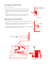
Battery Leads: Connect the red lead to the + battery terminal and the black lead to the - battery
terminal. The battery is tested every 180 seconds to ensure it is present and charged. A
low battery condition can be indicated at the keypad and/or communicated to the
central station.
Auxiliary Outputs: An auxiliary output wire harness is supplied for J5. There are 4 programmable output
pins and 2 power pins. Pins 1-4 will provide a ground path when activated. Pins 5 & 6
supply +12V DC. Do not exceed 100 mA per pin or 500mA total. These outputs are
intended to drive relays with a coil impedance of 500Ω or greater or any other device
requiring 100 mA or less. The outputs are not intended to power devices without the use
of a relay. It is acceptable to power an LED when a 1KΩ to 4.7KΩ, current limiting
resistor is wired in series. Use of Auxiliary Outputs is not permitted in a UL installation.
See System Triggers section for programming information.
Microphone Input: A microphone wire harness is supplied at J2. Consult the Specifications section to
determine compatible microphones. Up to 3 microphones can be wired in parallel to
each of the 3 microphone inputs. Please note, if multiple microphones (3 max) are wired
to a single microphone input, the microphones must be turned off and on as a group. It
is recommended to only wire 1 microphone to each of the 3 input channels allowing a
central station to have full control of each microphone during a two-way session. Use of
two-way voice is not permitted in a UL installation.
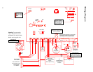
Power Switch: Located in the center of the control board is a black slide switch which controls all
power (including the battery) to the system. Right = ON; Left = OFF.
Siren Adjustment: The potentiometer marked "Siren" on the left side of the control board controls the
volume level of any system generated speech and the key depression feedback beeps.
Using a small screwdriver, turn the potentiometer to obtain the desired volume.
Clockwise increases volume. This adjustment will not the affect alarm notification
volume from the speaker during an activation.
Program Switch: Located in the upper right corner of the control board, this switch is used to return the
system to various defaults. Holding the button down and releasing after a specific
number of "beeps" will activate different system functions:
beeps Action
1 Return user code 1 to default: 1,2,3,4
3 Enter direct connect mode (Same as 9952 in program mode)
5 Return service (program) code default: 9,1,7,3
10 Default panel
other Three error beeps: no programming is affected.
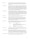
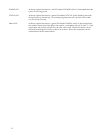
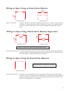
Hardwire Inputs: There are 8 hardware inputs on the control panel. Through programming, each input
can be wired in one of three ways: with a 4.7KΩ end-of-line resistor (EOLR), without an
EOLR, or with class-A 2-resistor supervision.
Two-Way Adjustment: The potentiometer marked "2-WAY VOL" controls the volume level of voice over the
phone line to the inside speaker during two-way communication or paging. Using a
small screwdriver, turn the potentiometer to obtain the desired volume. Clockwise
increases volume. This adjustment will not the affect alarm notification volume from the
speaker during an activation. Use of two-way voice is not permitted in a UL installation.
Upload / Download LED: At the top right of the board is a yellow LED labeled "U/D" which is illuminated when
there is a modem to modem connection during upload or download.