


E - 2
Index page
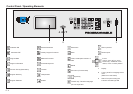
Control Panel / Operating Elements ............................................................... E - 4
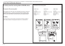
Explanation of Pictographs on the Display ...................................................... E - 5
Chapter Survey ............................................................................................... E - 6
Introduction ..................................................................................................... E - 7
Technical Data/Machine Layout/Transport and Installation .................... K1 - 1
of the Machine/Safety Relevant Machine Elements ...................................... K1 - 1
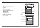
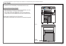
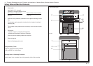
Machine Layout ............................................................................................K1 - 2
Plan .............................................................................................................. K1 - 3
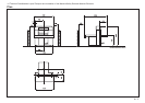
Transport and Installation of the Machine ..................................................... K1 - 4
Place of Installation ...................................................................................... K1 - 4
After the Installation of the Machine .............................................................. K1 - 4
Power Supply ............................................................................................... K1 - 5
Type plate ..................................................................................................... K1 - 6
Safety Relevant Machine Elements .............................................................. K1 - 7
Accident prevention warning labels at BAUM cutters. ................................... K1 - 8
Safety Relevant Machine Elements .............................................................. K1 - 8
Safety Signs ................................................................................................. K1 - 9
Technical Data ............................................................................................ K1 - 10
Permissible Environmental and Operating Conditions ................................ K1 - 10
Hydraulic Data ............................................................................................ K1 - 10
Safety Precautions ..................................................................................... K1 - 10
Residual Risk ............................................................................................. K1 - 10
Technical Data ............................................................................................ K1 - 11
Safety ...........................................................................................................K2 - 1
Start Up ....................................................................................................... K3 - 1
Switching Machine ON ................................................................................. K3 - 2
Turning Machine OFF ................................................................................... K3 - 2
Measurement Display and Measurement System ........................................ K3 - 3
Manual Operation .......................................................................................K4 - 1
Cutting Line Indicator, Mechanical with Clamp..............................................K4 - 2
Cutting Line Indicator, Optical ....................................................................... K4 - 2
Setting of Measurements (Backgauge Movement) by Hand ......................... K4 - 2
Clamp Pressure Adjustment ......................................................................... K4 - 3
Setting the Clamping Time ........................................................................... K4 - 3
Clamping and Cutting ................................................................................... K4 - 3
Light Barrier .................................................................................................. K4 - 4
Continuation: Light Barrier ............................................................................ K4 - 5
Clamping with False Clamp Plate ................................................................. K4 - 6
Automatic Operation ............................................................................... K5A - 1
Introduction .................................................................................................K5A - 2
Basic Displays ............................................................................................ K5A - 3
Basic Display: Program Data ......................................................................K5A - 3
Contin.: Basic Display: Program Data .........................................................K5A - 4
Basic Display: Program Information ...........................................................K5A - 5
Basic Display: Program Directory ...............................................................K5A - 6
Basic Display: Main Menu (Function Survey) ..............................................K5A - 7
Menu "Help":............................................................................................... K5A - 7
Explanation of pictographs .........................................................................K5A - 7
Cursor Movement in Basic Display ............................................................. K5A - 8
Automatic Backgauge Adjustment through Numerical Keyboard ................K5A - 9
Deletion of a Wrong Input ......................................................................... K5A - 10
Moving Backgauge to a Nominal Position (Positioning) ............................ K5A - 10
Input Error: Value of Nom. Backgauge Position too Low/High .................. K5A - 10
Selection of a Free Program/Display of the Next Free Program ............... K5A - 11
Selecting a Program .................................................................................K5A - 12
Continuing: Selecting a Program .............................................................. K5A - 13
Storage of Measurements ........................................................................ K5A - 14
Setting Up a Cutting Program, Example 1 ................................................ K5A - 15
Setting Up a Cutting Program, Example 2 ................................................ K5A - 16
Correction of an Input Error ...................................................................... K5A - 17
Automatic ON/OFF ...................................................................................K5A - 18
Running a Cutting Program ...................................................................... K5A - 19
Storing of Program Informations ............................................................... K5A - 20
Deletion of a Step Number........................................................................ K5A - 21
Deletion of One/Several Program(s) .........................................................K5A - 22
Deletion of Complete Memory .................................................................. K5A - 23
Inserting of Measurements into a Program ............................................... K5A - 24
Storing of Measurements According to Printed Image ..............................K5A - 24
Calculator Functions .................................................................................K5A - 25
Negative Sign ........................................................................................... K5A - 26
Using Backgauge Position of Calculations ...............................................K5A - 26
Machine Functions and Additional Functions (Menu Keys) ................ K5B - 1
Machine Function: Main Menu (Function Survey) ...................................... K5B - 2
Menu "Help":.............................................................................................. K5B - 2
Explanation of pictographs ........................................................................ K5B - 2
Service ...................................................................................................... K5B - 3