


Chapter 14: VRRP Configuration Guide
196 SmartSwitch Router User Reference Manual
Basic VRRP Configuration
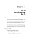
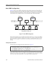
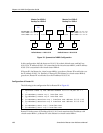
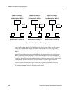
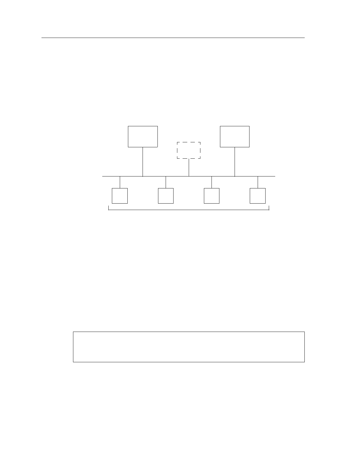
Figure 17 shows a basic VRRP configuration with a single virtual router. Routers R1 and
R2 are both configured with one virtual router (
VRID=1
). Router R1 serves as the Master
and Router R2 serves as the Backup. The four end hosts are configured to use 10.0.0.1/16
as the default route. IP address 10.0.0.1/16 is associated with virtual router
VRID=1
.
Figure 17. Basic VRRP Configuration
If Router R1 should become unavailable, Router R2 would take over virtual router
VRID=1
and its associated IP addresses. Packets sent to 10.0.0.1/16 would go to Router R2. When
Router R1 comes up again, it would take over as Master, and Router R2 would revert to
Backup.
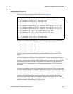
Configuration of Router R1
The following is the configuration file for Router R1 in Figure 17.
Line 1 adds IP address 10.0.0.1/16 to interface test, making Router R1 the owner of this IP
address. Line 2 creates virtual router
VRID=1
on interface test. Line 3 associates IP address
10.0.0.1/16 with virtual router
VRID=1
. Line 4 starts VRRP on interface test.
R1 R2
H1 H2 H3 H4
Default Route = 10.0.0.1/16
Master Backup
VRID=1
10.0.0.1/16
Interface Addr. =
10.0.0.1/16
VRID=1
;
Addr. =
10.0.0.1/16
Interface Addr. =
10.0.0.2/1
6
VRID=1
;
Addr. =
10.0.0.1/16
1: interface create ip test address-netmask 10.0.0.1/16 port et.1.1
2: ip-redundancy create vrrp 1 interface test
3: ip-redundancy associate vrrp 1 interface test address 10.0.0.1/16
4: ip-redundancy start vrrp 1 interface test