


Chapter 14: VRRP Configuration Guide
200 SmartSwitch Router User Reference Manual
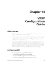
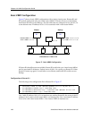
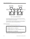
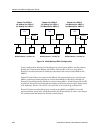
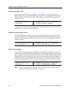
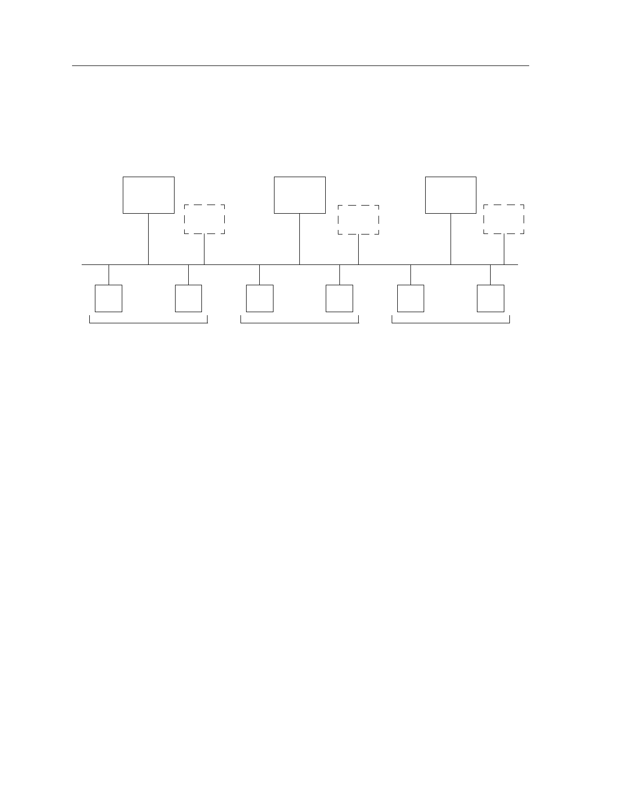
Figure 19. Multi-Backup VRRP Configuration
In this configuration, Router R1 is the Master for virtual router
VRID=1
and the primary
Backup for virtual routers
VRID=2
and
VRID=3
. If Router R2 or R3 were to go down,
Router R1 would assume the IP addresses associated with virtual routers
VRID=2
and
VRID=3
.
Router R2 is the Master for virtual router
VRID=2
, the primary backup for virtual router
VRID=1
, and the secondary Backup for virtual router
VRID=3
. If Router R1 should fail,
Router R2 would become the Master for virtual router
VRID=1
. If both Routers R1 and R3
should fail, Router R2 would become the Master for all three virtual routers. Packets sent
to IP addresses 10.0.0.1/16, 10.0.0.2/16, and 10.0.0.3/16 would all go to Router R2.
Router R3 is the secondary Backup for virtual routers
VRID=1
and
VRID=2
. It would
become a Master router only if both Routers R1 and R2 should fail. In such a case, Router
R3 would become the Master for all three virtual routers.
R1 R2
H1 H2 H3 H4
Default Route = 10.0.0.1/16
Master for VRID=1
Default Route = 10.0.0.2/16
1st Backup for VRID=2
R3
H5 H6
Default Route = 10.0.0.3/16
1st Backup for VRID=3
Master for VRID=2
1st Backup for VRID=1
2nd Backup for VRID=3
Master for VRID=3
2nd Backup for VRID=1
2nd Backup for VRID=2
VRID=1
10.0.0.1/16
VRID=2
10.0.0.2/16
VRID=3
10.0.0.3/16