


4-5
Cisco 12010, Cisco 12410, and Cisco 12810 Router Installation and Configuration Guide
OL-11496-01
Chapter 4 System Startup and Basic System Configuration
Powering On the Router and Observing the Boot Process
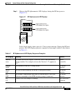
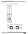
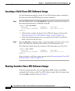
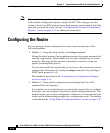
Step 4 Observe the RP alphanumeric LED displays during the RP boot process
(Figure 4-1).
Figure 4-1 RP Alphanumeric LED Displays
Each 4-digit display shows part of a 2-line system message. During the RP boot
process, the LED displays present a sequence of messages similar to that shown
in Table 4-1.
H10780
PROCESSOR
Upper alphanumeric
LED display (four digits)
Lower alphanumeric
LED display (four digits)
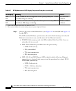
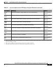
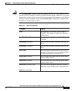
Table 4-1 RP Alphanumeric LED Display Sequence Examples
LED Display
1
Meaning Source
MROM
nnnn
The MBus microcode begins to execute; nnnn is the microcode
version number. For example, microcode Version 1.17 appears as
0117
2
.
MBus
controller
LMEM
TEST
Low memory on the RP is being tested. RP ROM
monitor
MEM
INIT
The size of main memory on the RP is being discovered. RP ROM
monitor
RP
RDY
The system is operational and ready to execute basic Cisco IOS
software commands at the ROM monitor prompt (rommon>).
RP ROM
monitor
RP
UP
A valid Cisco IOS image is running. RP Cisco IOS
software