


Page 12
iQ Series, Ultrasonic Hand Held Systems User’s Manual
Dukane Manual Part No. 403-577-01
Connecting Cables - Quick
Start Guide
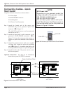
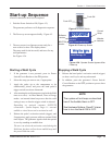
Complete the basic connections as shown below:
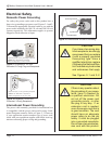
• AC Line Input
• HAND PROBE Connector
• Grounding Stud
• AC Power Cord Connection
Step 1. Attach the female end of the power cord
(200/240V only) to the generator’s power inlet
connector - A in Figure 3-1.
(The 100/120V model’s power cord is permanently
attached to the unit.)
Step 2. Attach the hand probe’s cable connector to the
generator’s HAND PROBE connection. - B in
Figure 3-1. Secure the connector to the system us-
ing the two jack screws attached to the connector
hood.
Step 3. Ground the generator chassis with a user–supplied
14-Gauge wire. Attach one end to the grounding
stud - C in Figure 3-1. Attach the other end to the
nearest grounded metal pipe or equal earth ground.
Step 4. Attach the male end of the power cord to a suit-
able line receptacle.
Optional Connections - See Page 14 for information
about the rear panel OUTPUTS connector.
NOTE
AC Power Inlet
Depending on your generator model, line
voltage required for the generator is either
100-120 VAC at 50/60 Hertz or
200-240 VAC at 50/60 Hertz.
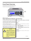
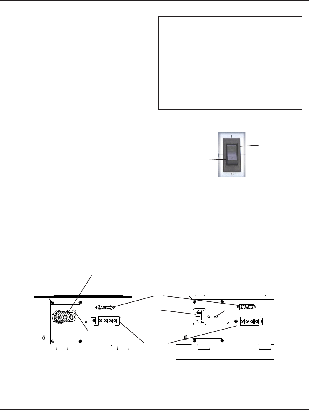
The unit has a power switch, and is pow-
ered ON whenever the AC line power is
live and the switch is in the ON position as
shown in Figure 3-2 below.
Figure 3-1 Generator Detail - Rear Views
Figure 3-2 Rocker-style Power Switch/Circuit Breaker
Push ON
Push OFF
HAND PROBE
OUTPUTS
HAND PROBE
OUTPUTS
REAR VIEW
200/24O VOLT MODEL
REAR VIEW
100/12O VOLT MODEL
C
A
B
Power Cord Strain Relief
Optional
Connections
C