


Page 74
iQ Series, Ultrasonic Hand Held Systems User’s Manual
Dukane Manual Part No. 403-574-01
No. Description Page
3-I Standard IEC AC Power Cord Part Numbers .................................................................13
3-II System OUTPUTS Connector Signals ...........................................................................14
6-I Tip Torque Unit Conversions ...........................................................................................38
6-II Stud Torque Unit Conversions ........................................................................................39
6-III Horn/Booster Torque Unit Conversions ...........................................................................41
7-I Pop-up Fault Status Screens - Manual Mode .................................................................49
7-II Pop-up Fault Status Screens - Time and Energy Modes ................................................50
9-I AC Power Requirements ................................................................................................60
List of Tables
List of Figures continued
5-18 Setup Maintenance - 1 ..................................................................................................30
5-18A Pop-up Load Defaults? ..................................................................................................30
5-19 Setup Maintenance - 2 ..................................................................................................30
5-20 Setup Maintenance - 3 ..................................................................................................30
5-21 Pop-up Overwrite Setup? ..............................................................................................30
5-22 Setup Maintenance 4 ....................................................................................................30
5-23 Save Curent Setup .......................................................................................................31
5-24 Store in Setup Maintenance .........................................................................................31
5-25 New Setup Stored ........................................................................................................31
6-1 Typical Hand Held Probes .............................................................................................35
6-2 Hand Probe, Horn and Tip .............................................................................................36
6-3 Probe, Booster and Horn ...............................................................................................37
6-4 Replaceable Tip Installation ..........................................................................................38
6-5 Stack Assembly Procedure ...........................................................................................40
6-6 Hand Probe Assembly and Disassembly ......................................................................40
6-7 Separating the Horn from the Booster ...........................................................................43
6-8 Removing a Replaceable Tip From the Horn ................................................................43
9-1 Generator Outline Drawing ............................................................................................57
9-2 Probes Outline Drawings and Dimensions ....................................................................58
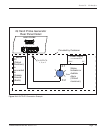
10-1 OUTPUTS Interface Example .......................................................................................65