


Page 14
iQ Series, Ultrasonic Hand Held Systems User’s Manual
Dukane Manual Part No. 403-577-01
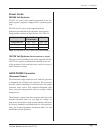
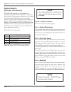
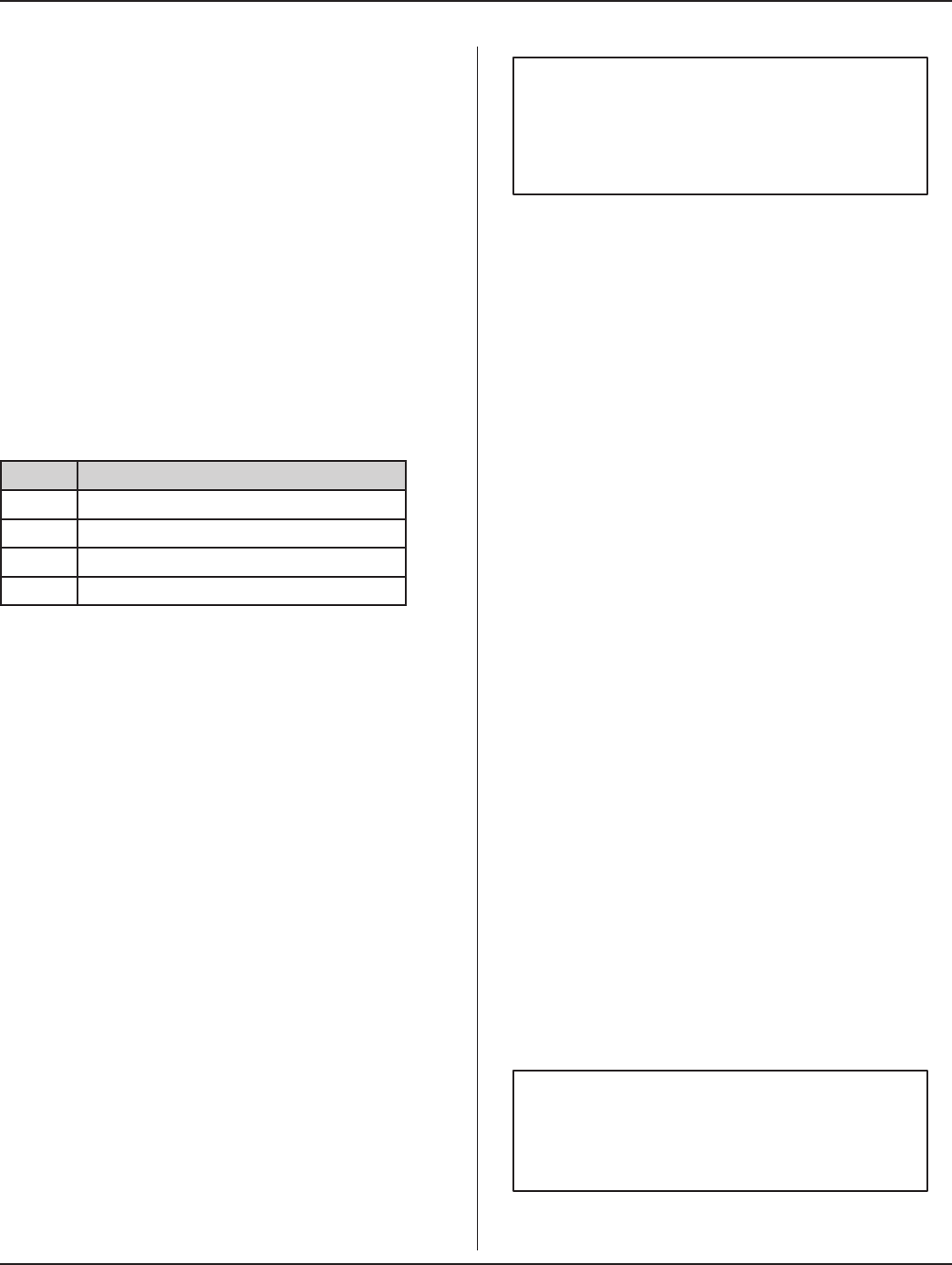
Pin Signal Name
0V Output Common
1 End of Weld Alarm
2 Any Fault Alarm
3 Bad Part
Table 3-II System OUTPUTS Connector Signals
Pin 0V (Output Common)
Pin 0V is connected to chassis ground.
Pin 1 (End of Weld Alarm)
Non-isolated NPN output that sinks current at the End of
Weld cycle. It activates when ultrasound switches off, or
at the end of a preset Hold period. The signal lasts for one
second, then deactivates.
Pin 2 (Any Fault Alarm)
Pin 2 is a non-isolated digital NPN status output that sinks
current to chassis ground if any fault condition is sensed.
This output is active until the start of the next cycle or
until ENTER is pressed if in non-latching fault mode.
In latching fault mode the user must press ENTER to clear
this output.
If a hardware fault like Over Temperature or a power fault
occurs, Any Fault is active until the fault is cleared in non-
latching fault mode. In latching fault mode, the user must
press ENTER to clear this output. However if the fault
persists, pressing ENTER has no effect.
Pin 3 (Bad Part)
Pin 3 is a non-isolated digital NPN status output that sinks
current to chassis ground if a Bad Part is detected. This
output is active until the start of the next cycle or until
ENTER is pressed if in a non-latching fault mode. It is
active until ENTER is pressed if in a latching fault mode.
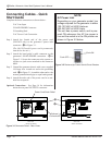
System Outputs
(Optional Connections)
The OUTPUTS connector is a four-position wire
receptacle-type terminal block. If needed, it can provide
the operator with basic system welding status. Everything
connected to the OUTPUTS connector is customer-
supplied. Typically indicator lights or sound modules are
powered by these output signals. (The lights or sound
modules can be mounted on widely available Stack Light
assemblies.) Each output signal is rated to operate on a
24VDC power source and can activate an attached load
up to a maximum of 500 mA.
Table 3-II lists the signal names.
NOTE
All outupt signals are non-isolated and
sink current to chassis ground when
activated.
NOTE
Refer to Figure 9-1, OUTPUTS Inter-
face Example, Page 65.