


Page 17
Section 4 – Controls and Connections
Dukane Manual Part No. 403-577-01
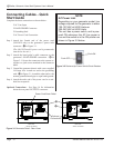
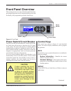
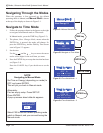
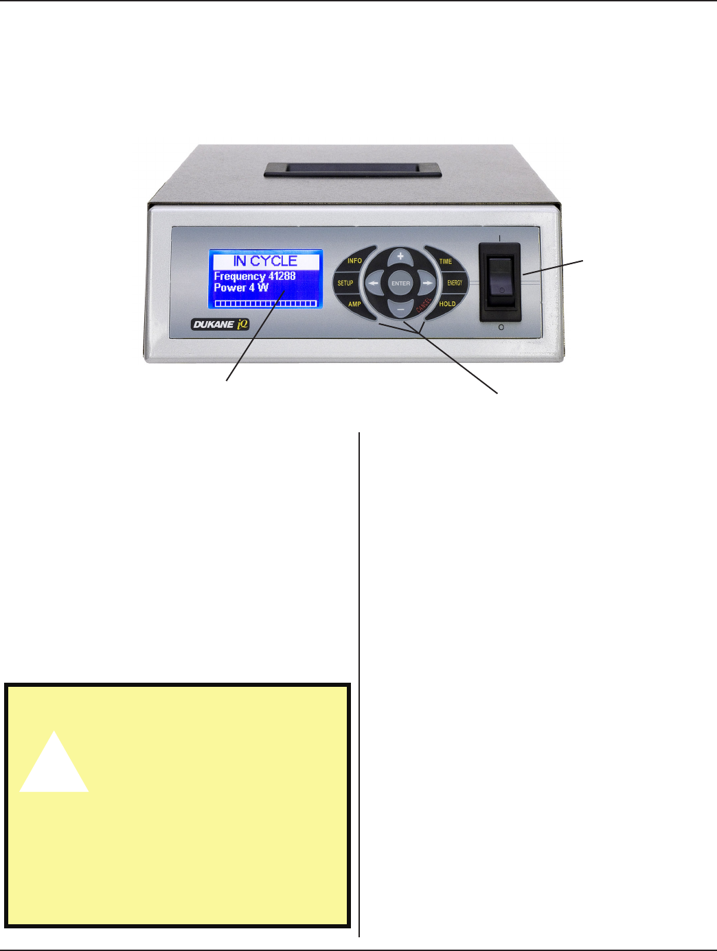
Figure 4-1 Front Panel
Front Panel Overview
This section gives an overview of the front panel functions:
powering the generator on/off; monitoring the process with
the display; and, programming with the control keys.
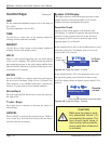
Control Keys
The control keys shown in Figure 4-1 and described
below, are used to display information, and to program
the generator.
INFO
Press this key to get system information or to modify the
hardware settings.
System Information - Identies the current
version of system software.
Hardware Settings - Select features that can be
turned on or off including the Audible Alarm or Fault
Latching options.
SETUP
Use the SETUP key to Load, Store, or Delete as many as
eight setups.
Power
Switch
Control Keys
LCD Display
Power Switch/Circuit Breaker
The power switch/circuit breaker has a rocker-style actua-
tor switch that will activate or deactivate the AC power
to the system. The power ON position is marked with the
internationally recognized I symbol, the power OFF posi-
tion is marked with the 0 symbol. This power switch also
integrates an appropriately sized over-current protection
circuit breaker function in the generator.
If an over-current condition trips the circuit breaker, it will
automatically switch to the OFF position. If the overload
current that caused the circuit breaker to trip is due to a
transient condition, the circuit breaker can be reset by
switching the actuator back to the ON position.
CAUTION
If when resetting the circuit
breaker afer it has tripped, it
immediately trips again, there
is likely an internal system
malfunction, and the generator
will need service. Do NOT re-
peatedly try to reset the circuit
breaker. If it trips, this will only
cause more damage to the
generator.
Continued