


Page 44
iQ Series, Ultrasonic Hand Held Systems User’s Manual
Dukane Manual Part No. 403-577-01
Booster Notes
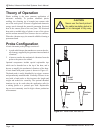
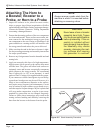
How to Tell the Booster
Input End from the Output
1. The depth of the threaded hole on the output end is
always deeper than the threaded hole on the input
end.
2. On an amplifying booster (gain > 1.0), the larger
diameter end is the input end. On a reducing booster
(gain < 1.0) the larger diameter end is the output end.
On a neutral acting booster the diameters are equal.
3. The cap screws on the booster mounting rings are
always inserted from the output end toward the input
end.
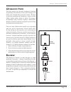
How to Tell if the Booster
Is Amplifying or Reducing
Boosters have a die-stamped number on their surface that
indicates their gain or reduction. If the number is greater than
1.0 (e.g. 1.5), it is an amplifying booster. If the number is
less than 1.0 (e.g. 0.6), it is a reducing or reverse booster.
A neutral booster has no gain and has 1.0 stamped on it. A
neutral or coupling booster is used to provide another probe
stack clamping location for added stability.
CAUTION
NEVER install a booster
upside down to change
an amplifying system to
a reducing system. The
boosters are dimensionally
asymmetric. They are tuned
from input to output to act
like an acoustic lens. Re-
versing them will not give the
expected results and may
cause damage to the system.