


System Verification
312359J 45
XM Setup and Troubleshooting Guide
The following setup information will help ensure the system is setup properly. See the XM repair-parts manual for trouble-
shooting and repair instructions.
Grounding
• Ground system to a true earth ground.
• Ensure incoming power is grounded.
Air Supply
• Use at least a 3/4 in. (19mm) ID air hose, no longer
than 50 feet (15m).
• Ensure the first gauge (supply) stays above 80 psi
(0.55 MPa, 5.5bar) while spraying.
• Ensure that the pump spray pressure regulator is set to
at least 35 psi (2.4 bar) for spraying.
• Ensure that the solenoid air filter/regulator behind the
air panel is set to at least 80-85 psi.
• Check that the air filter element in the solenoid air fil-
ter/regulator behind the air panel is clean.
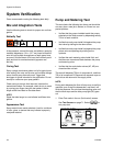
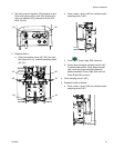
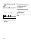
Calibration
• Adjust the B side fluid restrictor so that the calibration
bar graph averages center to right middle. This means
that the “B” dosing valve is open 25% to 75% of the
time.
• Ensure dosing valve needle packing nuts are not
adjusted too tight. They should be snug when there is
no fluid pressure on the valve.
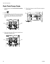
• If feed pumps are used, don’t use more than 250psi
(17 bar). Excess pressure adds double the amount of
pressure on only the upstroke of the XM metering
pump.
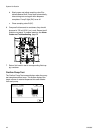
Motor Icing
Air motors accumulate ice in the exhaust valving and muf-
fler under hot and humid conditions or under cold ambient
conditions. It can cause pressure loss or motor stalling.
• The ‘B’ fluid pressure should always be 15% to 30%
higher than ‘A’ pressure.
• A larger pressure difference indicates ‘A’ motor icing.
• A smaller or negative pressure difference indicates ‘B’
motor icing.
• Ensure that the NXT motor De-Ice bleed valves are
open to bleed warm air across the ice.
• Ensure that the motor is left active when not spraying
to keep the internal bleed air working. Leave the motor
active in Spray mode or Manual mode to keep the
bleed air on.
Restrictions or Lost Pressure
• Always use filter screens in the XM pump lowers. Filter
style pumps come with 60 mesh screens. Optional 30
mesh elements are also supplied.
• Always use a gun filter. 60 mesh is provided in the gun.
Check that the static mixer is clean.
• Early mix manifolds (2009) had a 40 mesh screen on
the B side. The screen could plug with materials that
have filled ‘B’ side fluids.
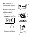
Remote Mix Manifold Applications
Ensure remote mix manifold outlet kit is installed. See XM
Repair parts manual. The kit includes outlet check valves
which isolate the pump pressure sensors from the outlet
hoses, and includes a ‘B’ side restrictor valve for the
machine outlet.
NOTE: Early remote manifold machines didn’t include
the ‘B’ restrictor valve from the factory.
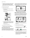
• Ensure that the ‘A’ and ‘B’ outlet hose sizes volume
balanced close to the mix ratio. Unbalanced hose sizes
can cause off ratio slugs at the mix manifold during
pressure and/or flow transitions. See XM Mix Manifold
Kits manual.
• If a minimum of integration and mix hose is used,
ensure that “Fast Dosing” is selected in the setup
screens
Software Version
• Ensure all modules in the system use software from
same token. Different software versions may not be
compatible.
• The latest software version for each system can be
found at Tech Support at www.graco.com.