Alarms
312359J 51
Alarms
View Alarms
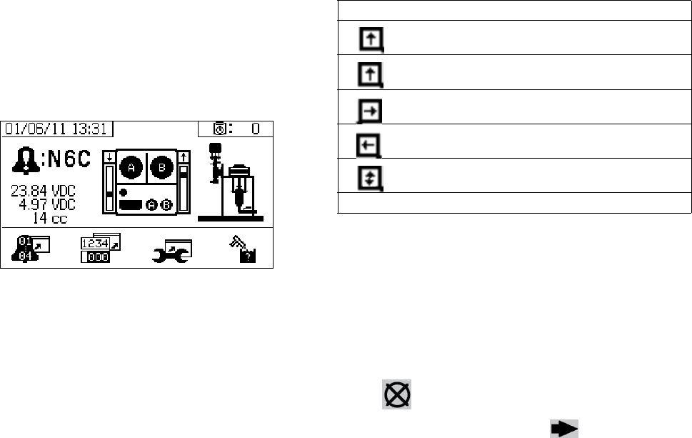
When an alarm occurs the alarm information screen
automatically displays. It shows the current alarm code
along with a bell icon. It also shows the alarm location
with top and side views of the sprayer.
There are two levels of alarms: warnings and advisories.
A bell icon indicates an alarm. A solid bell icon with an
exclamation point and three audible alerts indicate a
warning. And an outlined hollow bell icon and a single
audible alert indicate an advisory.
Advisories are notifications that require attention but not
immediately. Alarms require immediate correction;
therefore, sprayer operation automatically stops.
This screen also shows diagnostic information. There
are three lines of data on the left side. The top line
shows the power supply or alternator power supply. This
should be between 23-25 Volts for power supply sys-
tems and 10-14 Volts for alternator systems. The middle
line shows the sensor voltage. This should be between
4.9-5.1 Volts.
The center of the screen shows linear sensor vertical
bar graphs and reed switch information. The A side
information is on the left and the B side information is on
the right. Linear sensor position is displayed on the bar
graph that goes up and down when the pump moves.
This bar graph should move from top to bottom to match
each pump stroke.
The state of the two reed switches in each air motor are
shown with the arrow above each vertical bar graph.
Diagnose Alarms
See Alarm Codes and Troubleshooting for causes
and solutions to each alarm code.
Clear Alarms
Press to clear alarms and advisories. From the
alarm information screen, press to return to the
run (fluid control) screen.
Icon Function
Moving up
Moving down
Top changeover
Bottom changeover
One reed switch signal is missing
Blank: No reed switch signal


