


Appendix B
312359J 77
Appendix B
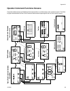
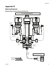
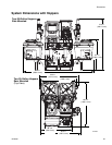
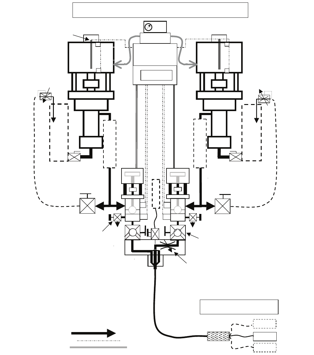
Metering Diagrams
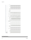
Metering Diagram without Remote Mix Manifold
N
XT
6500
Air
Motor
250 HF or
180 HP
A
N
XT
6500
Air
Motor
220 HF or
145 HP
B
psi
Sample
& Test
Valves
Control
Valves
Mix Manifold
Shut-off &
Check Valves
Mix
Manifold
Integration
Hose
3/8 x 25 ft
minimum
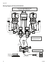
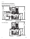
XM Metering Diagram
Air
Re
g
Circulation
Shut/Check
Controls
Linear
Transducers
Reed
S
witches
Double
Motor Pilots
Fluid Line
Control cable
Air Signal
rtd
rtd
Recirculation
Back P ssure re
Control
Settable ‘B’
Balancing
Restriction
H
O
P
P
E
R
H
O
P
P
E
R
H
E
A
T
E
R
H
E
A
T
E
R
Gravity Feed
Or
Pump Feed
psi
F
L
U
S
H
Whi
p
Hose
N
ote: Additional guns may only be added
after the integration hose and mixer
Mixers
S
p
ra
y
Gun
S
p
ra
y
Gun 2
S
p
ra
y
Gun 3