


-28-
G0451 14" Sliding Table Saw
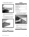
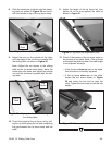
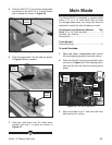
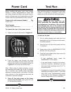
2. Install the lock plate as shown in Figure 40
using 4 of the screws removed in the previ
-
ous step.
Sliding Table
Components and Hardware Needed: QTY
T-Nut M12-1.75 ....................................................
1
Flat Washer 12mm .............................................
1
Push Handle M12-1.75 x 12 ................................
1
Edge Shoe ..........................................................
1
Hold Down ..........................................................
1
Sliding Table End Handle ...................................
1
Sliding Table Lock Plate .....................................
1
Tools Needed: QTY
Hex Wrench 4mm ...............................................
1
To assemble the sliding table components:
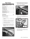
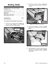
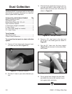
1. Remove the red shipping brace (Figure 39)
and the screws indicated. Set the screws
aside for use in the following steps.
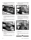
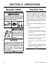
3. Install the end handle, as shown in Figure
41
, using the remaining screws removed in
Step 1
.
Figure 39. Sliding table.
Red Shipping
Brace
Figure 40. Installing the lock plate.
Lock Plate
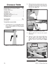
Figure 41. Sliding table end handle.
Table Lock
4. The sliding table is locked in place when the
table lock is in the position shown in
Figure
41. Rotate the table lock 180˚ to unlock the
sliding table.
End Handle