


G0646/G0647 50/65 Ton Ironworker
-21-
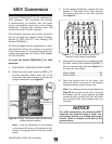
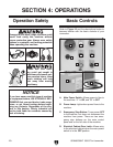
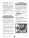
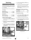
E. Motor Start Button: Turns the motor ON
when there is power to the machine
.
F. Motor Stop Button: Turns the motor
OFF.
G. Normal/Inch Switch:
In Normal position,
the beam moves to the end of the arc in
the direction selected, then returns to the
opposite end of the arc. In
Inch position, the
beam stops where it is when the foot actuator
is released or it has reached the end of the
arc—use this to "jog" the beam.
H. Punch/Notch Switch: Selects which direc
-
tion the beam moves when the foot actuator
is depressed.
I. Foot Actuator: Initiates the beam move
-
ment.
Operation Tips
• To produce quality cuts and avoid damage
to your machine, stay within the operational
capacities of your machine.
• Adjust the table guides, strippers, or hold-
downs to keep the workpiece from unexpect-
edly moving up during the operation without
restricting movement of the workpiece when
required for the next cut.
• Use liberal lubrication on the dies and
workpiece to reduce friction and wear on the
tooling.
• The quality of the cut edges are an immediate
indicator of the die condition. keep the dies
clean of debris and mill scale. Sharp tool
-
ing cuts cleaner and with less wear on the
machine.
• To avoid damage to the machine or tooling,
cut completely through the workpiece unless
you are using tooling designed for partial cut
-
ting.
• Dies are sharp! Always wear heavy leather
gloves when handling the dies to protect your
hands.
Punching
Use the punching station to perform general die
work, bar bending, corner notching, and tube
notching (additional tooling may be required for
some processes). The punching table and guides
accept a wide variety of workpiece shapes, and
the front portion of the table is removable for
flange punching. The limit stops are adjustable to
set the most efficient stroke length for your opera
-
tion (refer to Page 33
).
Use the following formula to calculate the maxi
-
mum punch diameter for the workpiece (all values
are in millimeters):
The machine constants are:
Model G0646 .................................................
330
Model G0647 .................................................
420
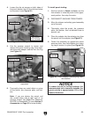
Using the Punching Station
1. Set the controls to Notch and Inch, then
raise the punching die up so that you can
insert the workpiece.
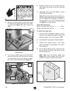
2. Rotate both knurled stripper adjustment
shafts together (see
Figure 17) to raise the
hold-down slightly higher than the thickness
of the workpiece.
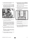
Figure 17. Typical punch station setup with a
workpiece mounted on the table.
Stripper Adjustment Shafts
Table Guides
punching station tips