


G0646/G0647 50/65 Ton Ironworker
-23-
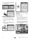
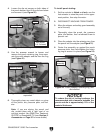
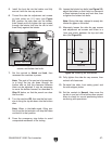
4. Loosen the die set screws on both sides of
the punch bolster, then lift the die from below
and remove it (see
Figure 20).
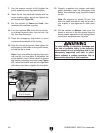
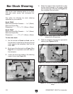
5. Use the spanner wrench to loosen and
remove the punch retaining ring, then sepa
-
rate the punch adapter and die from the ring
(see Figure 21).
Figure 21. Punch assembly removed and
separated.
Punch
Adapter
Retaining Ring
Figure 20. Punching die removed.
Punching Die
Set Screw
(1 of 2 shown)
Bolster
6. Thoroughly clean any metal debris or grime
off the punch, die, pressure plate, and bol
-
ster.
Note: If you are storing the punch and
die, protect them with a light coat of an
anti-rust product like G96
® Gun Treatment,
SLIPI
T®, or Boeshield® T-9 (see Section 5:
Accessories on Page 35
for more details).
To install punch tooling:
1. Set the controls to Notch and Inch, use the
foot actuator to raise the punch to the upper
-
most position, then stop the motor.
2. DISCONNECT MACHINE FROM POWER!
3. Move the stripper and safety guard assembly
out of the way.
4. Thoroughly clean the punch, die, pressure
plate, and bolster, then re-lubricate them to
prevent rust.
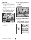
5. Place the adapter into the retaining ring, then
the punch into the adapter (see
Figure 21).
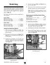
6. Center the assembly up against the punch
pressure plate, then hand-tighten the retain
-
ing ring to secure it in place (see
Figure 22).
Figure 22. Punch, adapter, retaining ring, and
die installed.
Die
Pressure
Plate
Punch
Assembly
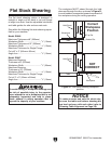
NOTICE
To reduce the risk of tooling breakage, the
recommended side clearance between the
punch and die is approximately 10% of the
material thickness.