


-26-
G0646/G0647 50/65 Ton Ironworker
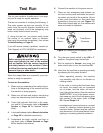
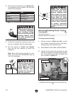
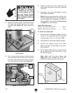
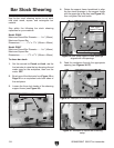
4. Remove the table guides, unthread the three
flat head cap screws securing the notch
-
ing table (see
Figure 26), then remove the
table.
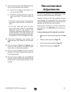
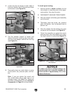
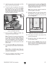
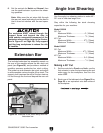
5. Put on heavy leather gloves, hold the bottom
dies (two side and one front) as you remove
the cap screws that secure them to the bol
-
ster, then remove the dies (see
Figure 27).
6. Support the top die as you remove the two
cap screws that secure it from the underside
of the die.
7. Thoroughly clean any metal debris or grime
off the dies and bolster.
Note: Before storing the punch and dies, pro
-
tect them with a light coat of an anti-rust prod
-
uct like G96® Gun Treatment, SLIPIT®, or
Boeshiel
d® T-9 (see Section 5: Accessories
on Page 35
for more details).
Notch Die Clearances
Bottom Front Die and Top Die ....................
3mm
Bottom Side Dies and Top Die ....................
1mm
To install the notch dies:
1. Set the controls to Punch and Inch, raise the
top die to its uppermost position above the
notching station, then turn the motor
OFF.
2. DISCONNECT MACHINE FROM POWER!
3. Remove the stripper plates, front safety
guard, and table, as described in the previ
-
ous subsection.
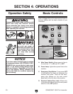
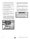
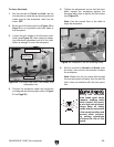
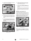
4. Put on heavy leather gloves, support the top
die up against the beam, then secure it with
the two cap screws.
Note: Make sure the bottom flange (see
Figure 28) of the included top die is posi-
tioned to the back and next to the beam.
Figure 26. Flat head cap screws that secure the
notching table.
The edges of ironwork-
er tooling are very sharp
and can quickly cut fin
-
gers and hands. Always
wear heavy leather gloves
when handling tooling to
avoid injury.
Figure 28. Top notching die orientation.
Figure 27. Notching dies.
Side Dies
Front Die
Cap
Screws
Top
Die
Bolster