


-50-
G0646/G0647 50/65 Ton Ironworker
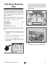
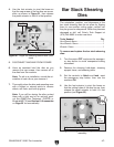
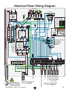
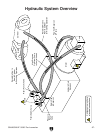
Figure 66. Hydraulic pressure relief and needle
valves.
Needle
Valve
Pressure
Relief
Valve
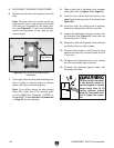
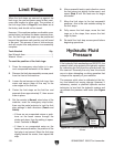
Limit Rings
When the limit stops are secured up against the
limit rings, the ram and beam move at their maxi
-
mum safe lengths to either side. The position of
the limit rings (refer to Page 33) have been set at
the factory and should not be moved.
However, if the machine makes a noticeable unex
-
pected noise just before the beam reverses direc
-
tion, the limit rings and stops may be positioned
beyond the maximum safe position and will need
to be reset. This process is one of trial-and-error
and will require time and patience to successfully
complete.
Tools Needed Qty
Hex Wrench 4mm ..............................................
1
Wrench 10mm ...................................................
1
To reset the position of the limit rings:
1. Press the emergency stop button in to pre-
vent unexpected movement of the beam.
2. Remove the limit stop assembly access panel
from the front of the machine.
3. Loosen the set screws on the limit rings, then
move and secure them all the way to the
outer edges of the limit bar.
4. Center the limit stops on the limit bar and
separate them approximately 2", then secure
them in place.
5. Set the controls to Normal, stand clear of the
machine, reset the emergency stop button,
then use the pedal actuator to test the limit
stop settings in both directions (
Punch and
Notch).
— If there are no unexpected noises or prob
-
lems as the beam moves through the
stroke and stops, then the setting is opera
-
tional. Continue to Step 6
.
— If there is an unexpected noise as the
beam reverses direction, the position of the
limit stop is not correct. Move the limit stop
slightly toward the center, then repeat this
step.
6. After successful tests in each direction, move
the limit stops just slightly further apart, and
repeat Step 5 until the tests are no longer
successful.
7. Move the limit stops to the last successful
positions—this is the safe outside setting for
the limit stops.
8. Fully secure the limit stops, move the limit
rings up to the stops, then secure the limit
rings in place.
9. Re-install the limit stop access panel before
beginning operations.
Hydraulic Fluid
Pressure
If the hydraulic fluid reaches beyond 3000 PSI, the
pressure relief valve protects the hydraulic system
by redirecting the fluid from the cylinder back into
the reservoir. Generally the only time this should
occur is when attempting a cutting operation that
is beyond the capacity of your machine.
The pressure relief valve is calibrated at the fac
-
tory and should not require change. However, if
necessary, contact a qualified hydraulic service
technician to load test the hydraulic system and
re-calibrate the pressure relief valve (see Figure
66).
limit rings
hydraulic fluid pressure