


-42-
G0646/G0647 50/65 Ton Ironworker
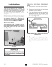
6. Reach through the opening in the top of the
reservoir left by the access plate and remove
the outlet filter from the reservoir.
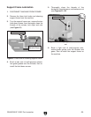
7. Thoroughly clean the filler cap, both filters,
and the inside of the reservoir with solvent or
mineral spirits. Make sure to wipe and dry all
fluid residue from the parts, inside the reser
-
voir, and the surrounding area.
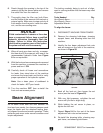
Beam Alignment
As the beam slides back and forth between the
front and rear panels, four bronze pressure pads
keep the beam and the attached tooling prop
-
erly aligned for safe and smooth operation. These
pressure pads wear under normal conditions and
require adjustment.
The tooling randomly being in and out of align
-
ment is a strong indicator that the beam may need
alignment.
Tools Needed Qty
Hex Wrench 8mm .............................................. 1
Hex Wrench 12mm ............................................
1
Adjustable Wrench ............................................
1
To align the beam:
1. DISCONNECT MACHINE FROM POWER!
2. Remove the shearing hold-down, shearing
support frame, and shearing table from the
machine.
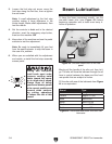
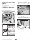
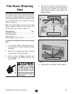
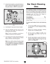
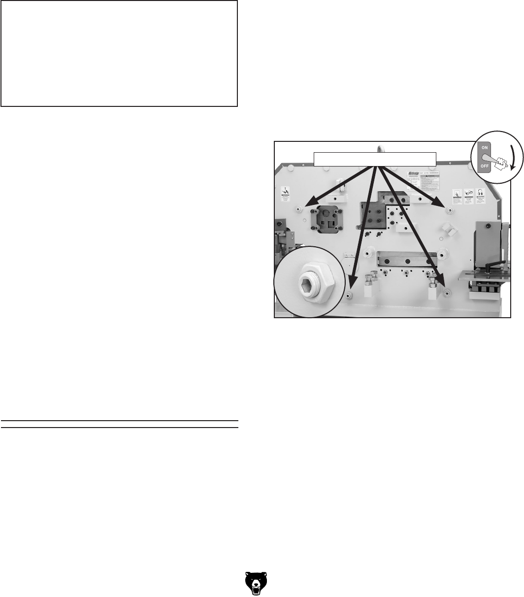
3. Identify the four beam adjustment lock nuts
and set screws on the front of the machine,
as shown in
Figure 58.
Figure 58. Beam adjustment lock nuts and set
screws.
Lock Nuts & Set Screws
4. Back off the lock nut, then loosen the set
screw (see the inset of
Figure 58).
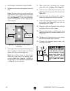
5. With very light pressure, re-tighten the set
screw until you feel a slight drag.
6. While holding the set screw in place, re-
tighten the lock nut.
7. Repeat Steps 5–6 for the rest of the beam
adjustment lock nuts and set screws.
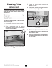
8. Re-install the shearing table, shearing sup-
port frame, and shearing hold-down.
beam alignment
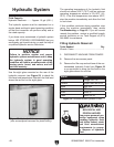
NOTICE
If fluid contamination is severe or there has
been a component failure, have a qualified
hydraulic technician thoroughly flush the
system. Failure to follow this instruction
could lead to premature wear of the hydrau
-
lic system and will void the warranty.
8. When all parts are clean and dry, re-assem-
ble them and fill the reservoir with one of the
recommended hydraulic fluids from
Figure
54 or an equivalent.
9. With the front and rear access panels removed
from the machine, re-connect the machine to
power and turn it
ON.
10. Carefully check all hoses and connections
for leaks, then stand clear of the machine
and move the beam back and forth to verify
proper operation of the hydraulic system.
Note: Use a clean piece of cardboard to
check for leaks—NOT your hands.
11. Turn the machine OFF, then re-install the
front and rear access panels.