


-2-
G0646/G0647 50/65 Ton Ironworker
INTRODUCTION
Foreword
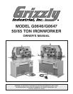
We are proud to offer the Model G0646/G0647
50/65 Ton Ironworker. This machine is part of a
growing Grizzly family of fine machinery. When
used according to the guidelines set forth in this
manual, you can expect years of trouble-free,
enjoyable operation and proof of Grizzly’s com-
mitment to customer satisfaction.
The specifications, drawings, and photographs
illustrated in this manual represent the Model
G0646/G0647 when the manual was prepared.
However, owing to Grizzly’s policy of continuous
improvement, changes may be made at any time
with no obligation on the part of Grizzly.
For your convenience, we always keep current
Grizzly manuals available on our website at
www.grizzly.com. Any updates to your machine
will be reflected in these manuals as soon as they
are complete.
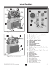
Functional Overview
The Model G0646/G0647 Ironworker is a versatile
metal-cutting machine that cuts mild steel stock at
five separate stations: 1) punching, 2) notching, 3)
bar stock shearing, 4) angle iron shearing, and 5)
flat stock shearing.
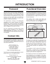
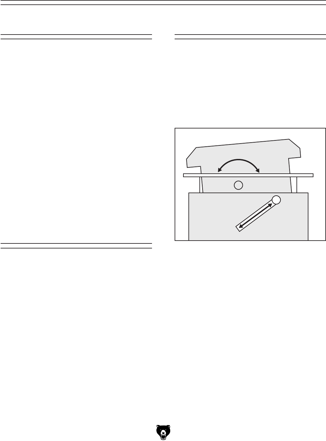
This machine uses a single, large beam that
moves through an arc from side-to-side and is
driven by the hydraulic ram (see Figure
1).
We stand behind our machines. If you have any
service questions, parts requests or general ques
-
tions about the machine, please call or write us at
the location listed below.
Grizzly Industrial, Inc.
1203 Lycoming Mall Circle
Muncy, PA 17756
Phone: (570) 546-9663
Fax: (800) 438-5901
E-Mail: techsupport@grizzly.com
If you have any comments regarding this manual,
please write to us at the address below:
Grizzly Industrial, Inc.
C
/O Technical Documentation Manager
P.O. Box 2069
Bellingham, WA 98227-2069
Email: manuals@grizzly.com
Contact Info
The beam is mounted with the appropriate dies
for each station. As the beam reaches the end of
the arc, limit switches automatically reverse the
hydraulic flow and move the beam back. A pres
-
sure relief valve protects the hydraulic system
if the operation exceeds the capabilities of the
machine.
The workpiece is held in place with hold-downs,
table guides, or strippers that are designed spe
-
cifically for each station. All stations accept a wide
variety of punch and die configurations.
Exit panels on the rear of the machine allow for
long workpieces to be processed at the shear-
ing and cutting stations. In addition, an extension
assembly mounts above the exit panels of the bar
and angle iron shearing stations for measured
repetitive work.
Figure 1. Movement of the beam.