


G0646/G0647 50/65 Ton Ironworker
-27-
5. Install the front die into the bolster and fully
secure it with the two cap screws.
6. Thread the side die adjustment set screws
on both sides out 2–3 turns
(see Figure
29), position the side dies into the bolster,
then thread and fully tighten the cap screws
through the bolster and into the die to hold
them firmly against the bolster.
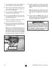
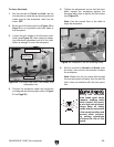
10. Loosen the bolster hex bolts (see Figure 29),
adjust the bolster so that there is a clearance
of 3mm between the top and front dies, then
re-tighten the bolster hex bolts.
Note: During this step, attempt to evenly dis-
tribute the gaps on the sides.
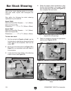
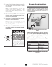
11. Alternately loosen the side die cap screws
and adjustment set screws until there is a
1mm gap evenly between the top and side
dies (see
Figure 30).
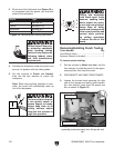
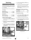
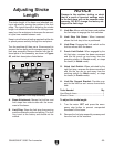
Figure 29. Notching side die set screw, cap
screws, and bolster hex bolts.
Set Screws
Cap
Screws
Bolster Hex Bolts
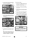
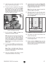
7. Set the controls to Notch and Inch, then
reconnect the machine to power.
Note: The goal of the next set of procedures
is to bring the top die down through the
bottom dies so that the clearance between
them can be adjusted. It may be necessary
to move the bolster forward, as described in
Step 10 below, so that the punch can clear
the front die.
8. Turn the machine ON, then use the foot actu-
ator to bring the top die down into the bottom
dies.
Note: When in the Inch mode, lifting your
foot from the foot actuator will stop the beam
and hold it in that position.
9. Press the emergency stop button to avoid
unexpected movement of the tooling.
12. Fully tighten the side die cap screws, then
recheck all clearances.
13. Re-install the table, front safety guard, and
the side stripper plates.
14. Set the controls to Normal, then move the
top die in and out of the bottom dies several
times to check for correct positioning before
continuing with operations.
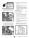
Figure 30. Notching die clearances.