


-4-
Model G0795 (Mfd. Since 02/15)
Controls &
Components
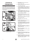
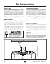
Figure 1. Control panel and spindle speed
controls (right view).
B
A
F
G
Figure 2. Control panel and spindle speed
controls (left view).
N
M
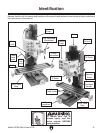
Refer to Figures 1–2 the following descriptions to
become familiar with the basic controls and com-
ponents of this machine. Understanding these
items and how they work will help you understand
the rest of the manual and stay safe when operat-
ing this machine.
H
I
J
K
L
C
D
E
A. Mode Switch: Sets the spindle mode to
either Drill, Stop or Tap.
B. High/Low Range Knob: Selects either high
or low spindle speed range.
C. Coarse Downfeed Handle: Typically used
for drilling operations for rapid drilling or
plunge cutting. Spring assisted return auto-
matically returns spindle to top position when
released.
D. Downfeed Selector Knob: Selects fine or
coarse downfeed controls. When loosened,
coarse downfeed is engaged; when tight-
ened, fine downfeed is engaged.
E. Spindle Speed Knob: Selects one of three
spindle speeds in the selected speed range.
F. E-Stop Button: Cuts power to the spindle
motor and remains depressed until reset.
Twist clockwise to reset.
G. OFF Button: Stops spindle rotation.
H. POWER Indicator Light: Illuminates when
machine is connected to power.
I. Fine Downfeed Handwheel: Moves spindle
up and down for precise Z-axis control when
milling. Micrometer collar graduated in incre-
ments of 0.001".
J. Depth Stop and Scale: Limits depth of
spindle downfeed stroke to preset height as
indicated on the scale.
K. Depth Stop Adjustment Knob: Adjusts
position of depth stop.
L. Quill Lock Lever: Locks quill at desired
height above workpiece.
M. Headstock Elevation Crank Handle: Moves
headstock up and down for proper spindle
position during setup.
N. Spindle Direction Buttons: Controls spindle
direction of rotation (as viewed from above).
The spindle must be completely stopped
before either button is pushed.